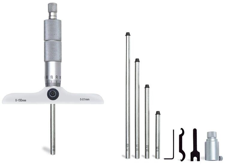
The right instrument depends on the feature you must measure, the drawing tolerance, the available access, and the uncertainty your inspection system can accept. By the end, you will be able to specify the range, rod, base, contact geometry, verification method, and digital functions before comparing models.
Key takeaways
- Define the feature, datum, tolerance, and bottom geometry before choosing a range.
- Use a depth micrometer for broad access; compare depth gauges and bore gauges for other features.
- Match the base, rod, and contact tip to the slot, hole, shoulder, or groove.
- Verify zero, reference standards, data output, and calibration support before purchase.
Start with the feature, tolerance, and measurement specification
Define the feature before you define the range: blind-hole depth, recess depth, slot depth, shoulder height, or groove depth. Record the datum surface, nominal dimension, upper and lower limits, contact location, and whether the bottom is flat, curved, rough, or obstructed. That specification determines the base and rod geometry.
Then compare the tolerance with the instrument’s complete measurement specification. Check resolution, maximum permissible error, repeatability, and uncertainty at the actual working depth with the intended rod and base installed. A claim such as ±0.005 mm over one range does not automatically apply to a longer rod or a reading near the range limit.
ISO 13385-2:2019 should appear in the procurement specification, alongside range, resolution, maximum permissible error, and calibration-certificate requirements.
| Tool | Useful when | Wrong choice when |
|---|---|---|
| Digimatic depth micrometer | A stable base and controlled depth reading are required | The base cannot seat on the datum |
| Mechanical depth micrometer | You need a robust, non-battery tool and can read the thimble consistently | Electronic records or rapid data capture are required |
| Digimatic depth caliper | Features are accessible and speed matters more than micrometer-level control | A narrow base or caliper beam rocks in the recess |
For a quality inspection depth micrometer, run a short repeatability and reproducibility study on representative parts. Have one inspector repeat several locations, then have other inspectors repeat the setup; variation usually exposes rocking, burrs, force, or datum problems.
That evidence—not display resolution alone—answers which digital depth micrometer for fits quality inspection in Kolkata. A digital display without the required Digimatic connector, protocol, cable, or software still leaves you transcribing results.
Compare the three depth-measurement tools against the job
Choose a Digimatic depth micrometer when the feature has a defined reference face and the tolerance demands controlled, repeatable depth readings. Its digital display removes reading-parallax errors, but a 0.001 mm resolution display is not ±0.001 mm accuracy.
| Tool | Best fit | Where it loses |
|---|---|---|
| Digimatic depth micrometer | Blind holes, recesses, shoulders, and close-tolerance depth checks with interchangeable rods | Rod changes add cleanliness, seating, range, and calibration-control risks |
| Mechanical depth micrometer | Inspection where battery-free operation, ruggedness, or direct tactile feedback matters | Slower readings and thimble-reading errors; parallax can affect interpretation |
| Digimatic depth caliper | Quick checks across slots, steps, recesses, and varied features where speed and access matter | Less suitable when the part tolerance requires micrometer-level force and repeatability |
Compare accuracy at the actual working range, with the intended rod and base installed. A stated ±0.005 mm error over one range does not automatically apply to a longer rod, another base, or a reading near the range limit.
A Digimatic depth caliper is the better choice when you measure many feature types and speed outweighs the tightest uncertainty budget. Use a mechanical depth micrometer when electronics, batteries, or data output create more risk than value.
Whatever the digimatic depth micrometer options, keep the spindle normal to the reference surface and seat the base fully. Tilting introduces cosine error; the display cannot correct it. Compare the instrument’s stated error, repeatability, and calibration uncertainty with the part tolerance, not with the display resolution alone.
Match the rod, base, and contact geometry to the feature
Choose rod length and contact shape from the feature’s datum and bottom, not the micrometer’s nominal range. For a blind hole, use the shortest rod that reaches the bottom without letting the base touch surrounding material. A longer rod adds flexure and a new seating, cleanliness, and calibration-control risk.
| Feature | Rod and contact choice | Base or contact check |
|---|---|---|
| Blind hole | Flat-ended rod for a flat bottom; spherical end for a curved bottom | Keep the base clear of the rim and confirm the rod reaches the specified depth |
| Groove | Narrow rod or rounded contact that fits between the groove walls | Prevent either wall from steering the contact |
| Slot | Contact narrower than the slot, with a length that reaches its floor | Keep the base fully supported on the reference face |
| Shoulder | Flat-ended rod for a defined step; use a rounded end only when the drawing defines point contact | Bridge the shoulder without rocking the base |
| Uneven recess | Spherical or rounded contact to localise the reading | Record the specified contact location; otherwise repeatable readings can still be functionally wrong |
Judge a quality inspection depth micrometer with the intended rod and base installed, at the actual working depth. An accuracy claim such as ±0.005 mm over one range does not automatically apply to a longer rod or a different base.
Test representative parts at several locations with multiple inspectors; variation exposes rocking, burrs, poor contact, or an undefined datum.
Control setup errors that digital displays cannot remove
Zero the instrument on the same clean, flat reference surface used to establish the inspection datum. A 0.001 mm display does not provide ±0.001 mm accuracy; use the manufacturer’s maximum permissible error and the calibration laboratory’s uncertainty statement.
- Wipe the base, rod, reference plate, and workpiece. Remove burrs and coolant film before closing the measuring contact.
- Place the base fully on the datum surface and check that it does not rock. Keep the spindle normal to the surface; tilting creates cosine error and reports an excessive depth.
- Apply the same gentle force for every reading, using the ratchet or friction mechanism rather than hand pressure. Excess force can deflect the setup or seat the rod differently.
- Allow the instrument and part to reach the inspection-room temperature before zeroing. Steel expands about 11.5 µm per metre per °C, so a 100 mm dimension changes approximately 1.15 µm per 1 °C.
For digital depth micrometers in Kolkata, wipe condensation and corrosive residue after use, then store the instrument dry. A sealed or coolant-resistant design helps but does not replace cleaning.
Repeat each location after lifting and reseating the base. Have the same operator measure several locations, then repeat the setup with another inspector. Large variation points to rocking, contact force, burrs, bottom geometry, or an unclear datum—not display resolution.
Specify verification, data handling, and supplier support
Approve the instrument only after the supplier matches the measurement task, uncertainty, data route, and service plan to your inspection process. A 0.001 mm display does not deliver ±0.001 mm accuracy.
1. In the datasheet, record the measuring range, resolution, maximum permissible error, repeatability, base dimensions, rod lengths, operating temperature, and protection against coolant or moisture. Reference ISO 13385-2:2019, not merely “digital depth micrometer.”
2. Demand a calibration certificate that names the instrument and each supplied rod, shows serial numbers, calibration date, applied points, results, traceability, expanded uncertainty, and the laboratory’s coverage of the stated maximum permissible error. Confirm whether rod changes require separate verification.
3. Test the digital interface before ordering. Confirm the connector, output protocol, cable, data-request control, software compatibility, and whether readings can enter your SPC or electronic inspection record. A digital display alone may leave operators transcribing every value.
4. Run a short repeatability and reproducibility study on representative parts: one inspector repeats locations, then another repeats the setup. Investigate variation from rocking bases, burrs, contact force, bottom geometry, or unclear datums before blaming resolution.
5. Ask Yamayo Instruments to document replacement rods, calibration turnaround, battery and cable availability, service location, and cleaning guidance for humid Kolkata conditions. Confirm dry storage and wipe-down procedures for rods, bases, and battery compartments.
Compare Digimatic depth micrometer options on these written responses before approving digital depth micrometers in Kolkata.
Related products
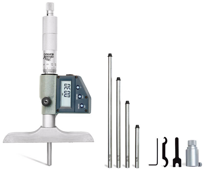 | Depth Measurements Digimatic Depth Micrometers The Digimatic Depth Micrometer is a high-precision digital measuring instrument designed for accurate measurement of... View product → |
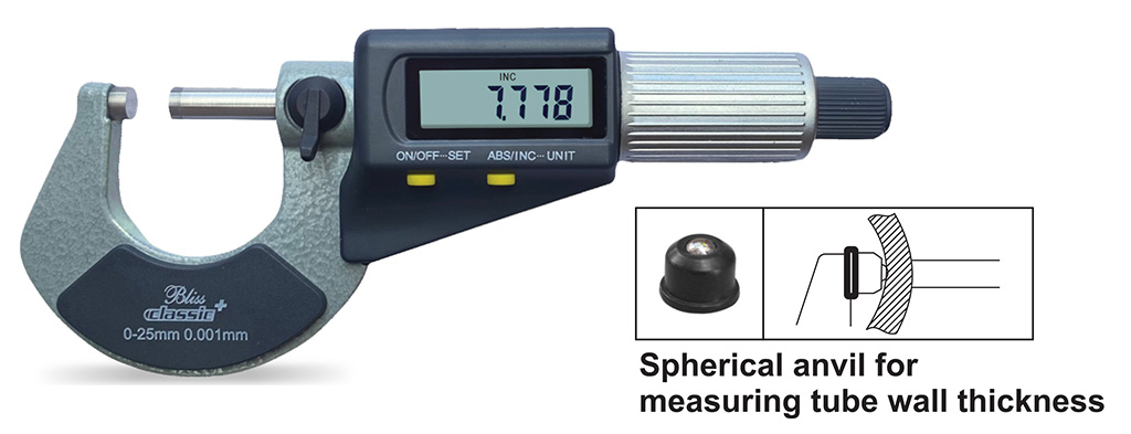 | Micrometers Digimatic Micrometers The Digimatic Micrometer is a high-precision digital measuring instrument designed for accurate external dimension measurement... View product → |
Frequently asked questions
How do you choose a digital depth micrometer for quality inspection in Kolkata?
Define the feature first: blind-hole, recess, slot, shoulder, or groove. Record the datum, nominal depth, limits, contact geometry, and bottom condition, then select the range, base, rod, and contact point that reach the feature without tilting.
What is the difference between a digital depth micrometer and a depth gauge?
A digital depth micrometer uses a screw-driven spindle for controlled contact and fine adjustment. A depth gauge suits faster comparative checks across surfaces, while the correct choice depends on tolerance, feature access, repeatability, and required resolution.
Which base and rod geometry should a depth micrometer have?
Choose a broad base for stable measurement on flat datums, a narrow base for restricted access, and rods or extensions that reach the bottom without contacting the side wall. Match the contact tip to flat, curved, rough, or obstructed bottoms.
How do you control depth micrometer measurement errors?
Clean the datum and contact, check zero, keep the base fully seated, align the spindle with the measurement axis, use consistent measuring force, and repeat readings. Verify performance with a suitable reference standard before release.
What should you ask a supplier about digital depth micrometers in Kolkata?
Ask for the measuring range, resolution, accuracy specification, base and rod options, contact geometry, battery and data-output details, calibration documentation, spare parts, and local service or verification support.