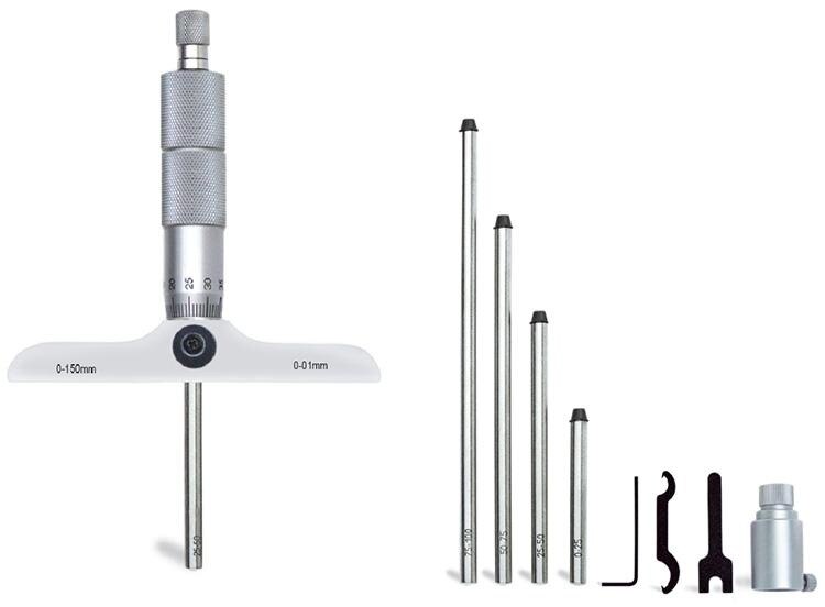
The right instrument depends on more than a 0.001 mm display: the feature’s opening, reference surface, depth range, contact geometry, and required uncertainty all affect the result. By the end, you will be able to match a digital depth micrometer to the feature, define a repeatable inspection method, and identify when another depth-gauging design is safer.
Key takeaways
- Match the base to the reference surface and the contact to the feature bottom.
- Choose a range and rod system that reach every required depth without excess movement.
- Use a depth caliper for quick checks; choose a micrometer for controlled, repeatable readings.
- Verify zero, clean the datum, and repeat measurements using the same seating force.
Match the base and contact to the feature
Choose the base and contact that let the digital depth micrometer for quality inspection reference a stable plane and reach the intended bottom without rubbing the opening. Keep the base fully supported on a clean, deburred reference surface; chips, burrs, sealant, or weld spatter create a false datum and a systematic error.
| Feature | Suitable geometry | Main risk |
|---|---|---|
| Blind hole or small bore | Narrow base with a slim or pointed contact | The rod touches the wall, chamfer, or bore taper instead of the bottom |
| Narrow slot or keyway | Narrow base that sits inside the opening | A wide base will not seat or will bridge the slot |
| Counterbore or shoulder | Base sized to rest on the correct shoulder, with a contact reaching the lower face | The base may reference the wrong step |
| Stepped face | Compact base that remains on one level | A wide base can bridge a local step |
| Broad flat surface | Wider base with a flat or spherical contact | A large base may fail to enter a pocket |
| Angled bottom or curved surface | Pointed, ball, or application-specific contact | Contact on a slope gives a depth that changes with position |
Chamfers, tapered holes, angled bottoms, and curved surfaces require a deliberate contact point; a general depth micrometer can measure an unintended slope. For pits, corrosion, weld undercut, rough castings, or blasted surfaces, use a pit-depth gauge, pointed contact, defined reference shoe, or controlled surface-conditioning method.
A depth micrometer for inspection is unsuitable when its flat base rides over surrounding texture.
Choose the range, rod system, and display features
A 0–150 mm tool suits an accessible feature with a tight tolerance better than a 0–450 mm model. Longer rods reach deeper, but deflect more easily and normally carry wider accuracy tolerances. Choose reach only after checking whether the rod can enter squarely without rubbing the opening.
| Range | Approximate inch range | Inspection implication |
|---|---|---|
| 0–150 mm | 0–6 in | Shorter, stiffer reach for accessible features and tighter tolerances |
| 0–300 mm | 0–12 in | Extra reach with greater deflection sensitivity |
| 0–450 mm | 0–18 in | Deep features; verify wider stated accuracy and support requirements |
These digimatic depth micrometer sizes are commonly available with interchangeable rods, fixed ranges, or longer-spindle designs. Interchangeable rods reduce the number of instruments required, but every change adds a joint, seating surface, and rod-identification requirement. A fixed-range tool is preferable when setup time and configuration control matter more than range economy.
Compare digital depth micrometer options by specified accuracy or maximum permissible error, not resolution alone. A 0.001 mm or 0.00005 inch increment does not make the measurement accurate to that increment.
- Check graduated-sleeve visibility, digital-display readability, and whether a ratchet or friction thimble gives consistent control.
- Identify the output: a manufacturer-specific port, USB or wireless output, or a system that records instrument ID, operator, units, timestamp, part number, and characteristic number.
- Select the smallest range that reaches the feature reliably; stable seating reduces uncertainty more effectively than a finer display increment.
Decide between a digital depth micrometer and a depth caliper
Choose a digital depth micrometer for qc when a tight tolerance, rigid seating, and repeatable contact matter more than speed. Choose a digimatic depth caliper when you need rapid checks across varied features and access is restricted.
| Option | Strength | Best fit |
|---|---|---|
| Digital depth micrometer | Rigid base, controlled spindle travel, defined contact force, stronger repeatability | Acceptance decisions when the base sits squarely on a stable reference face |
| Digimatic depth caliper | Faster operation, slimmer access, flexible positioning | Wider-tolerance checks, mixed features, and high inspection volume |
Define the method before measuring: approach from one direction, specify seating pressure, set contact force, and state whether the result is recorded at first contact or after a ratchet-controlled reading. Rocking the base, dragging the spindle across the bottom, changing ratchet pressure, or measuring at an angle can change the result.
A ratchet controls spindle force; it cannot correct poor seating, a non-flat bottom, a tapered bore, or a rod touching the wall. If the bottom is uneven, agree whether the reading means first contact, the minimum depth, or a defined point.
Allow the part, base, and spindle to reach temperature equilibrium before long measurements. Thermal expansion differs between those components, so measure near the stated reference temperature and control drafts, warm hands, and recently machined parts.
Use a repeatable inspection and verification procedure
A reading is fit for an inspection record only when the method, instrument condition, and reference are controlled—not because the display is stable. Use this sequence for a digital depth micrometer for inspection:
1. Record the part number, characteristic, rod identification, measurement range, and units.
2. Let the instrument and workpiece reach the stated reference temperature. Temperature differences between the base, spindle, and part can shift the result.
3. Remove chips, oil, sealant, weld spatter, burrs, and raised material from the base and reference face. Contamination changes the plane from which depth is measured.
4. Place the base fully on the reference face and check for rocking. The work instruction must define the seating technique and what to do if the base rocks or sits tilted.
5. Zero the instrument, then align the rod with the true bottom. Do not drag the rod across the feature or allow it to touch a wall.
6. Apply consistent force and take the number of readings specified by the work instruction. That instruction must set the acceptable spread and state whether readings use first contact or a ratchet-controlled force.
7. After changing rods, verify zero and confirm that the rod is fully seated and correctly identified. A stable display does not prove accuracy.
Before acceptance use, check representative points across the working range with a depth standard, step master, or controlled fixture. A flat gauge block alone does not reproduce depth-reference geometry. If results disagree with the calibrated reference, quarantine the instrument, identify affected measurements, and investigate contamination, rod seating, temperature, and calibration status.
Set intermediate checks by risk and observed stability, tightening them for high-use, coolant-exposed, abrasive, or product-acceptance instruments.
Turn the specification into a purchasing decision
Start with the inspection record, not the catalogue. For a digital depth micrometer for quality inspection, document:
- Feature type, minimum opening, required depth, tolerance, and reference-face condition
- Contact shape, base footprint, access limits, and expected temperature
- Inspection volume and required data-record format
For each digital depth micrometer options candidate, compare maximum permissible error across the working range, resolution, repeatability, rod length and increments, base width, spindle clearance, force-control method, display or graduated-sleeve visibility, output protocol, and calibration support. A 0.001 mm display increment does not prove 0.001 mm accuracy.
Fixed-range tools suit configuration control: one defined setup, fewer rod changes, and simpler operator instructions. Interchangeable rods reduce instrument count, but each change adds a joint, seating surface, and rod-identification check.
| Option | Strength | Trade-off |
|---|---|---|
| Fixed-range | Stable configuration and traceability | More instruments for multiple depths |
| Interchangeable-rod | Broad coverage with fewer instruments | Setup, seating, and identification controls |
Yamayo Instruments can help compare dimensional-inspection instruments against these feature and traceability requirements; request the manufacturer’s accuracy specification, calibration method, rod identification procedure, reference temperature, and data-output details before purchase.
Select the instrument that minimises method uncertainty through stable seating and suitable contact geometry, not the one with the smallest advertised display increment.
Related product
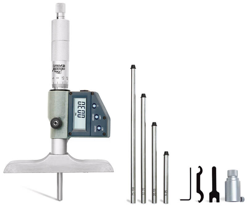 | Depth Measurements Digimatic Depth Micrometers The Digimatic Depth Micrometer is a high-precision digital measuring instrument designed for accurate measurement of... View product → |
Frequently asked questions
How do you match a digital depth micrometer base and contact to a feature?
Use a base that sits fully on a clean, deburred reference plane, then choose a contact that reaches the feature bottom without rubbing the opening or contacting a sloped wall.
Which range and rod system should you choose for quality inspection?
Select a range covering the shallowest and deepest required features, and choose a rod system that reaches those depths with minimal extensions and no interference.
When is a digital depth micrometer better than a depth caliper?
Choose a digital depth micrometer when contact stability, controlled measurement, and repeatability matter; use a depth caliper for faster checks across larger or less demanding features.
What procedure produces repeatable depth inspection readings?
Clean the datum and contact, verify zero, seat the base consistently, apply controlled force, take repeated readings, and record the feature, instrument ID, and result.