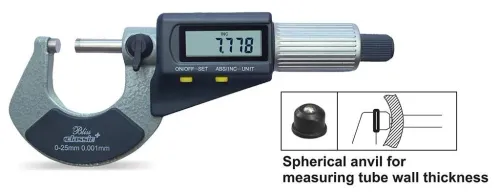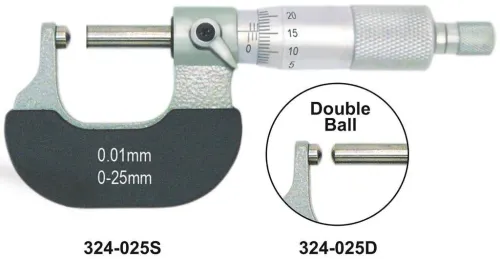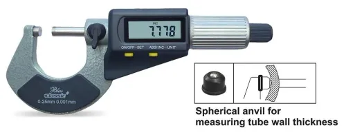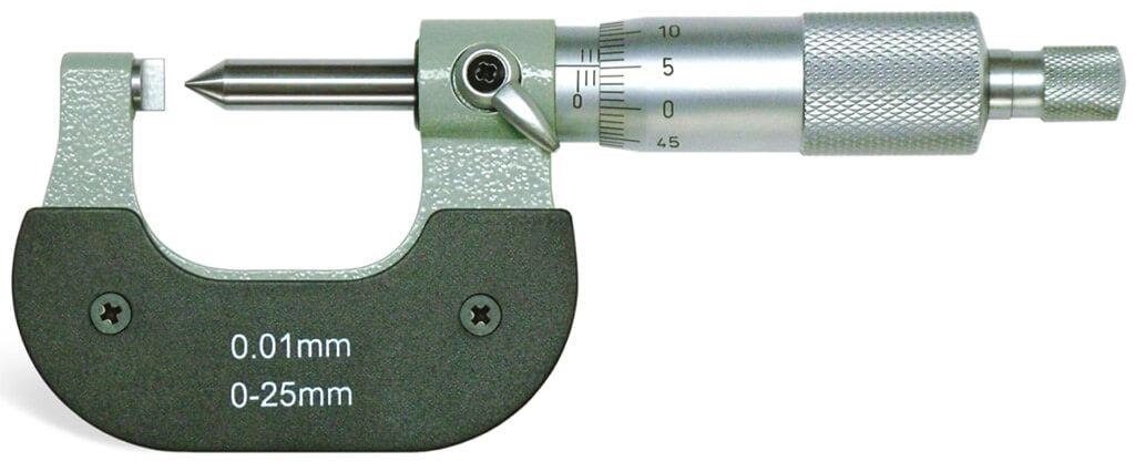
The correct instrument depends on what the contacts must reach and what surface they must seat against. By the end, you will be able to distinguish terminal-crimp measurement from groove, keyway, and drill-web measurement, specify the geometry that matters, and choose a suitable alternative when a micrometer is not the right tool.
Key takeaways
- Use crimp height micrometers on formed conductor and insulation crimps.
- Use point micrometers for narrow webs, grooves, and recessed features.
- Match the measuring faces to the feature, not just the nominal range.
- Measure consistent locations with clean, stable parts and controlled force.
Crimp geometry or restricted access: what separates the two designs?
Choose a crimp height micrometer for the formed conductor-crimp section of a wire terminal; choose a point micrometer when a narrow, recessed feature demands pointed access. The terminal drawing determines the crimp location and acceptable height, not a universal dimension.
| Design | Measurement purpose | Contact geometry and access |
|---|---|---|
| Crimp height micrometer | Conductor-crimp or specified insulation-crimp height | Shaped anvil and spindle match the terminal barrel; contacts the crimp axis |
| Point micrometer | Drill web, groove, slot, keyway, or narrow shoulder | Pointed or conical faces enter the feature without bearing on adjacent faces |
| Ordinary outside micrometer | Broad external thickness or diameter | Flat or cylindrical faces suit accessible outside surfaces |
A point micrometer can give a misleading crimp reading if its tips bottom in the terminal cavity, touch only an edge, or cannot align across the crimp. Its nominal resolution does not correct unsuitable contact geometry.
When comparing crimp height micrometers in Jaipur with a point micrometer in Jaipur, specify the terminal part number or drawing, conductor-crimp range, wire-size range, and required anvil and spindle form. State whether the tool is for production checks or laboratory validation, then verify calibrated accuracy and repeatability over the working range; zeroing alone proves neither.
What to inspect before buying a crimp height micrometer
Buy against the terminal or applicator drawing, not a generic “crimp micrometer” label. The drawing identifies the conductor-crimp section, permitted height, wire-size range, material, plating, and measurement location; the value is not interchangeable across terminals. State the terminal part number and whether the instrument is for production checks or laboratory validation.
| Specification | What to inspect | What goes wrong if mismatched |
|---|---|---|
| Anvil and spindle | Contact shapes must seat on the formed conductor crimp, not the insulation wings or bellmouth | You measure a nearby feature and accept a false height |
| Range and throat | Conductor-crimp height range, wire size, and access depth must cover the terminal | The spindle bottoms out or cannot reach the specified section |
| Force control | Use the manufacturer’s specified measuring force with a ratchet or friction thimble | Hand pressure changes readings on soft or springy crimps |
| Resolution and performance | Compare resolution with specified accuracy, repeatability, and measurement uncertainty | Extra decimal places disguise poor agreement between operators |
| Calibration | Require calibration across the working range and suitable standards, not zeroing alone | A zeroed instrument can still be inaccurate |
For crimp measurement tools, confirm the instrument’s contact geometry before comparing price or display type. A point micrometer suits a groove or web; a crimp-height model suits the terminal section defined by the drawing. This distinction matters when searching for micrometers for automotive terminals in Jaipur.
Request the conductor-crimp range, anvil and spindle geometry, throat depth, measuring force, output type, calibration certificate, and check-standard requirements. Include the measurement orientation in the work instruction; otherwise operators may measure a wing edge or transition and produce repeatable but irrelevant readings.
How to measure conductor and insulation crimp heights correctly
Place the terminal with the conductor crimp facing the instrument’s anvil and the specified measurement section directly under the spindle. Do not measure across the insulation support, bellmouth, transition zone, or a terminal wing edge; each can produce a believable but invalid value.
1. Confirm the terminal part number, wire cross-section, applicator, die set, and measurement location on the terminal or applicator drawing. The correct height is specific to that combination, not a universal wire-gauge value.
2. Strip or position the sample exactly as the process requires, then orient the terminal so the spindle and anvil contact the formed conductor-crimp section at the stated cross-section. Keep the terminal square; tilting changes the reading.
3. Close the spindle with the ratchet or friction thimble until the specified measuring force is reached. Avoid squeezing the terminal, and keep both contacts on stable, formed metal rather than on a bellmouth or uneven edge.
4. Record the reading, instrument identification, wire size, terminal part number, and sample orientation. Repeat according to your inspection plan and investigate variation before adjusting the applicator.
5. Inspect insulation-crimp height separately. Check insulation support, seal position, conductor protrusion, wire brush, bellmouth, and terminal damage against the drawing or visual criteria; a conductor-crimp reading proves none of these.
Selecting micrometers for automotive terminals requires the terminal family, plating, insulation, stranding, and tooling specification. A request for crimp height micrometers in Jaipur should state those details, not merely “automotive crimp micrometer.”
How to specify and use a point micrometer on webs and grooves
A reliable point-micrometer reading starts with tips that fit the feature without touching its adjacent faces. Specify the included tip angle, tip radius, tip width, spindle travel, throat depth, measuring range, resolution, and contact force; a sharp point can indent a thin drill web or soft slot wall instead of measuring it.
| Feature | Contact requirement | Common error |
|---|---|---|
| Drill web | Tips meet the web faces squarely at the intended section | Measuring near the edge or allowing the point to tilt |
| Slot or groove | Tip width and angle fit the bottom without touching the side walls | Reading the wall-to-wall distance instead of the bottom width |
| Keyway | Throat depth reaches the keyway and the spindle aligns across its width | Seating on a corner, burr, or radius |
Use this sequence for each reading:
- Clean oil, chips, and burrs from the feature; debris can hold the tips apart.
- Place the anvil against one face, then bring the spindle in along the feature’s measurement axis.
- Keep both contacts normal to the surfaces. Rock the micrometer gently through the smallest reading rather than forcing the tips into position.
- Apply the same ratchet or friction-thimble action each time. Record the reading only after both tips seat without visible deflection or marking.
- Check zero and verify the relevant range with a calibrated standard; zeroing alone does not establish accuracy.
When sourcing a point micrometer in Jaipur, state the feature drawing, tip geometry, force, range, and access direction. Do not substitute general crimp measurement tools: their tips can bottom in a terminal cavity or fail to align with the crimp axis.
Choosing the right instrument for the feature and the inspection process
Match the instrument to the feature, access direction, and decision the reading must support.
| Option | What it measures | Choose it when |
|---|---|---|
| Crimp-height micrometer | Formed conductor-crimp height at the terminal drawing’s specified location | You are checking a wire terminal and need shaped contacts that seat on the crimp barrel |
| Point outside micrometer | Groove, keyway, slot, drill-web, or spline thickness | A pointed or conical tip can reach the feature without touching adjacent faces; this is the correct point micrometer in Jaipur for restricted geometry |
| Ordinary outside micrometer | Accessible external dimensions between broad, parallel faces | The part has flat or cylindrical surfaces and needs general dimensional control |
| Caliper | Fast outside, inside, step, or depth checks | You need screening or setup information, not the highest repeatability for a critical crimp |
| Depth micrometer | Recess or shoulder depth from a reference face | The specification controls depth rather than wall thickness or external size |
| Optical system | Profile, edge position, contour, or non-contact dimension | Contact tips would deform the feature, block access, or miss a complex profile |
When sourcing crimp measurement tools, state the terminal part number or drawing, conductor-crimp height range, wire-size range, contact and anvil geometry, resolution, digital or scale output, calibration requirement, and whether use is production checking or laboratory validation.
Ask for calibration over the working range, suitable standards, specified accuracy, repeatability, and uncertainty; zeroing alone proves none of these. Yamayo Instruments can help compare the geometry against that specification rather than treating similar names as interchangeable.
Related products
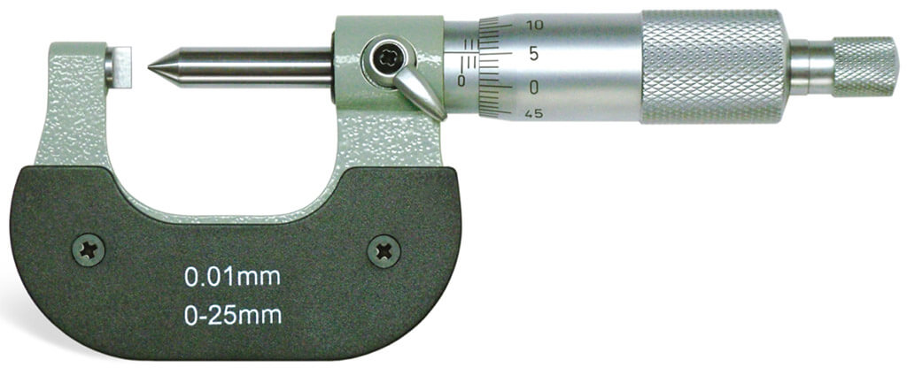 | Micrometers Crimp Height Micrometers The Crimp Height Micrometer is a specialized precision measuring instrument designed for accurate measurement of crimp... View product → |
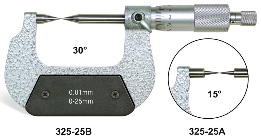 | Micrometers Point Outside Micrometers The Point Outside Micrometer is a specialized precision measuring instrument designed for measuring web thickness of... View product → |
Frequently asked questions
What separates a crimp height micrometer from a point micrometer?
A crimp height micrometer is shaped for access to formed wire-terminal crimps. A point micrometer uses pointed measuring faces to reach narrow webs, grooves, and recessed features.
How do you measure conductor and insulation crimp heights correctly?
Use the terminal drawing to identify each measurement location, clean and position the terminal consistently, close the instrument with controlled force, and record conductor and insulation heights separately.
What should you inspect before buying a crimp height micrometer?
Check its measurement range, anvil and spindle geometry, access clearance, resolution, repeatability, locking method, calibration documentation, and compatibility with your terminal sizes.
When should you use a point micrometer on webs and grooves?
Choose a point micrometer when standard flat measuring faces cannot enter the feature without contacting adjacent surfaces. Specify the point angle, tip radius, range, and clearance required.
Related product
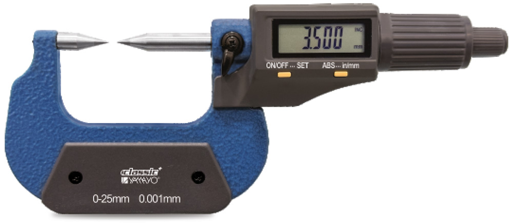 | Micrometers Digimatic Point Outside Micrometer Digimatic Point Outside Micrometer The Digimatic Point Outside Micrometer is a high-precision digital measuring instrument specifically designed for... View product → |