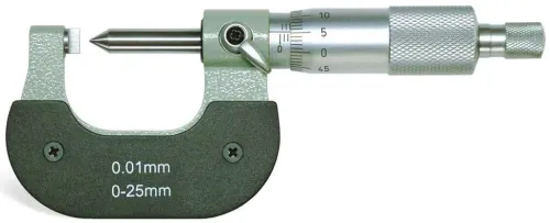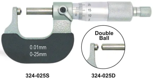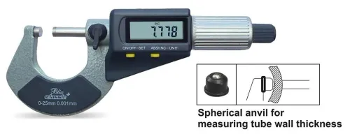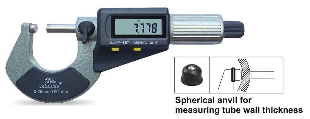
A wireless reading is useful only when it reaches the correct inspection record with enough context to prove what was measured, by whom, and with which instrument. You will learn how to build the measurement workflow, test compatibility, control technique and temperature, and evaluate a supplier before putting Bluetooth micrometers on the shop floor.
Key takeaways
- Confirm Bluetooth, Digimatic, receiver, and software compatibility before purchase.
- Record part revision, characteristic ID, nominal size, tolerance, and measurement value.
- Control measuring force, temperature, cleanliness, and alignment before accepting readings.
- Test the complete micrometer and software workflow on your shop floor.
From a Micrometer Reading to a Verified Inspection Record
A complete workflow starts by pairing the micrometer or its attached transmitter with the intended receiver, then opening the inspection application on a tablet, PC, or gateway. Select the correct part number, revision, and characteristic ID before pressing the instrument’s data button for one reading.
A successful Bluetooth connection proves only that devices communicate. It does not prove that one button press, a continuous stream, or a completed-record export is being handled correctly. Confirm what the system sends: a numeric value alone, or the value with units, timestamp, operator ID, part number, characteristic ID, instrument ID, and pass/fail status.
| Receiver | Best use | Confirm before acceptance |
|---|---|---|
| Tablet application | Mobile inspection at the machine | Supported operating system, Bluetooth profile, and active inspection template |
| PC application | Fixed workstation and SPC entry | Driver or SDK, application mapping, and whether data appears as a keyboard, COM port, or service |
| Gateway | Multiple instruments feeding MES or quality software | Pairing limit, device mapping, buffering, and recovery after network loss |
Use this acceptance sequence:
- Record three repeated readings from the same component and verify each enters the intended characteristic.
- Press the transmit button again deliberately; confirm whether the system creates one new record, duplicates the value, or ignores the retry.
- Interrupt the connection, take a reading, reconnect, and verify whether the value is marked missing, queued, duplicated, or assigned to the wrong operation.
- Replace or remove the battery, wake the Bluetooth micrometer, and repeat the test.
Reject the setup until every result can be traced to the intended component and operation.
Check the Bluetooth, Digimatic, and Software Compatibility Chain
Verify the entire signal path before buying: micrometer output, transmitter, Bluetooth link, receiving device, and inspection software. Digimatic is an instrument data interface, not proof of built-in Bluetooth capability. A “Digimatic outside micrometer Bluetooth” setup may use a model-specific transmitter or adapter attached to the output port.
1. Match the micrometer’s output connector and Digimatic protocol to the approved transmitter or adapter. Confirm the transmitter model, supported Bluetooth profile, operating distance, pairing limit, and whether it needs a separate receiver or gateway.
2. Check how the software receives data. Bluetooth Low Energy may require a vendor app, software development kit, gateway, or service-profile support; it may not appear as a keyboard or Windows COM port. Confirm compatibility with the intended Android or iOS device, Windows PC, MES, SPC package, or inspection application.
3. Run a live test using your actual device, application, inspection template, and measurement operation. Send a reading, close and reopen the connection, and confirm that the correct value reaches the intended characteristic.
4. Test shop-floor conditions rather than relying on the quoted range. Metal enclosures, machine tools, coolant, body blocking, and radio congestion can reduce reliable distance. Check auto-sleep, battery replacement, low-battery transmission, pairing limits, and reconnection after wake-up.
A cable may outperform Bluetooth at a fixed workstation. Mobile stations gain convenience only when the transmitter remains available and the software recovers cleanly from lost connections.
Design Records That Preserve Tolerance and Traceability
A wireless value is not traceable until the system ties it to the part, requirement, person, and instrument. Wireless transfer reduces transcription mistakes; it does not prove which component was measured or whether someone altered the result. This is the minimum record for micrometers for digital inspection:
1. Identify the job with the part number, part revision, and component serial number or batch number. Add the characteristic ID so the value cannot be confused with another feature.
2. Store the nominal size, upper limit, lower limit, unit, measured value, and pass/fail result. Record the timestamp, operator or station, instrument ID, calibration status, and any manual override with its reason and author.
3. Confirm that one button press creates one reading in the intended characteristic. Keep the transmitted event, not only the final pass/fail summary, so an auditor can reconstruct what happened.
4. If the connection drops, a retry creates a duplicate, the wrong part number is active, or the value enters the wrong characteristic, stop the operation. Identify the affected record, mark the exception, preserve the original event if the software allows it, and repeat the measurement against the correct component.
5. Assign each instrument a documented calibration interval and retain traceable calibration records, including the instrument identifier, calibration date, results, and next due date.
6. Run repeatability and reproducibility or another measurement-system analysis when your quality system requires it. A clean data trail cannot rescue a measurement process that produces inconsistent results.
Control Contact Technique and Temperature Before Trusting the Value
Wireless capture changes the record, not the measurement. Contact technique still determines whether the value deserves trust.
1. Clean the anvil and spindle faces before measuring. Remove chips, oil, and burrs from the faces and the workpiece; a burr can produce a false high reading or damage the contact surfaces. Place the micrometer square to the feature, measure at the specified location, and check multiple locations when taper or variation is relevant.
2. Close the spindle with the same ratchet or friction-thimble force every time. Excessive force compresses soft material and distorts results; inconsistent force destroys repeatability. Bluetooth cannot correct cosine error, dirt, taper, a misplaced measurement, or an over-tightened spindle.
3. Allow the workpiece and micrometer to reach the specified reference temperature before comparison, and write the stabilization time into the work instruction. Keep your hands off small instruments during measurement because hand heat can shift the reading.
Steel expands roughly 11–12 µm per metre per °C, so a 100 mm steel dimension changes about 1.1–1.2 µm per °C.
Before purchase, obtain the instrument’s permissible error, repeatability, flatness, parallelism, resolution, environmental limits, and calibration results. Do not qualify a micrometer from display resolution alone: a 0.001 mm display does not prove 0.001 mm accuracy. Require a defined calibration interval and traceable calibration records.
Choose the Complete System and Test It on Your Shop Floor
Choose Bluetooth for mobile inspection stations, but keep a cable or spare instrument for recovery. A controlled workstation with a fixed PC often gets better uptime from wired Digimatic or USB capture.
| Option | Strength | Constraint |
|---|---|---|
| Bluetooth | Mobile use; fewer transcription errors | Batteries, pairing limits, receiver cost, radio and cybersecurity controls |
| Wired Digimatic | Reliable point-to-point transfer | Cable routing and compatible interface required |
| USB | Direct PC connection | Driver, port, software, and interface requirements |
| Manual recording | Works during outages | Transcription errors and weaker traceability |
Test auto-sleep, wake-up transmission, battery replacement, network loss, and the fallback process. Define who records a reading when the connection fails, how missed or duplicated values are identified, and how access, pairing, encryption, firmware, and application permissions are controlled.
For anyone seeking a bluetooth micrometer supplier in Jaipur, require a demonstration on your own tablet, PC, receiving software, inspection template, part range, and tolerance records. Ask for:
- Exact micrometer and transmitter models, compatibility list, Bluetooth profile, pairing limit, receiver cost, and operating-system support
- Calibration documentation, interval, spare batteries, replacement transmitters, and local service response
- A written recovery procedure for missed, duplicated, or wrongly assigned readings
Yamayo Instruments can be assessed against those same evidence requirements rather than catalogue claims. Confirm repeated readings and retries during acceptance.
A connected micrometer records an external dimension only; it does not replace ultrasonic, eddy-current, radiographic, or magnetic-particle testing for hidden defects.
Frequently asked questions
How does a Bluetooth micrometer become a verified inspection record?
Pair the micrometer or transmitter with the receiver, open the inspection application, select the part revision and characteristic ID, then send the reading using the instrument’s data button. Verify that the recorded value matches the displayed value and includes the correct operator, time, and instrument details.
What compatibility checks are needed for a Digimatic outside micrometer with Bluetooth?
Check the micrometer’s output interface, Digimatic compatibility, Bluetooth profile, transmitter or receiver requirements, operating system, inspection software, and gateway connection. Confirm that the complete chain works together rather than checking Bluetooth on the micrometer alone.
Which details make a digital inspection record traceable?
Store the part number, drawing revision, characteristic ID, nominal dimension, upper and lower tolerances, measured value, unit, instrument ID, calibration status, operator, timestamp, and disposition.
How do contact technique and temperature affect micrometer readings?
Clean the anvil, spindle, and workpiece; align the micrometer squarely; use the ratchet or friction thimble consistently; and allow the part and instrument to reach the agreed reference temperature, commonly 20 °C for dimensional metrology.
How should you evaluate micrometers for digital inspection before deployment?
Run representative parts through pairing, measurement capture, tolerance evaluation, data storage, export, and failure recovery. Test connection range, duplicate readings, battery changes, rejected values, and operator identification on the shop floor.