Choose the instrument from the feature and tolerance, not from the assumption that one tool is universally more accurate. By the end, you will know when pointed contacts are necessary, when a dial caliper is sufficient, how to avoid common inspection errors, and what to specify when sourcing locally.
Key takeaways
- Use a point micrometer for narrow grooves, roots and recessed features.
- Use a dial caliper for fast checks on accessible outside, inside and depth dimensions.
- Keep contacts square, clean, and lightly seated to avoid false readings.
- Choose another tool for threads, rough surfaces, soft materials or tighter tolerances.
Match the instrument to the automotive feature
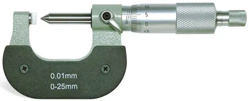
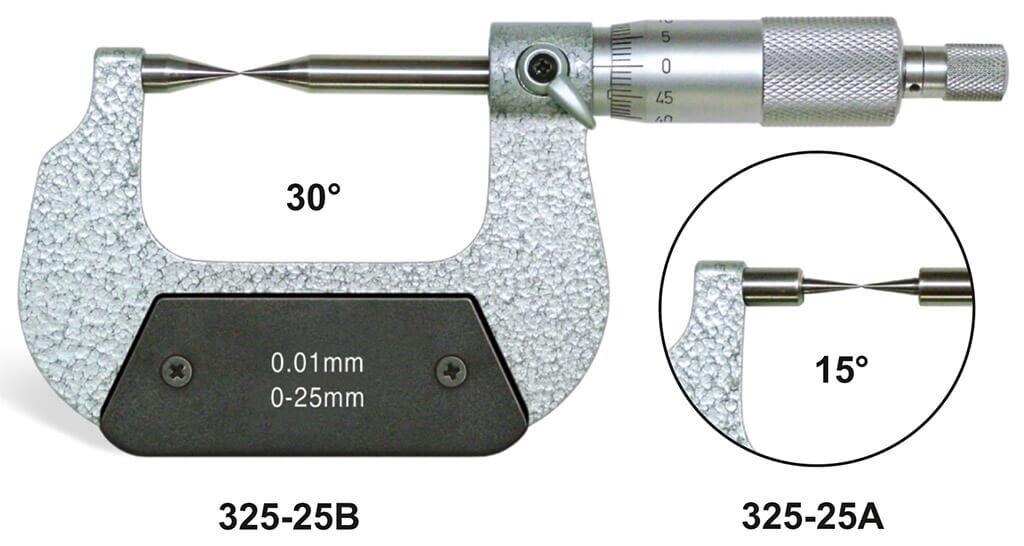
Use a point micrometer when the feature is recessed or too narrow for ordinary contacts; use a dial caliper for fast checks of accessible dimensions. A pointed spindle and pointed anvil reach a groove or root without resting on its shoulders, while broad caliper jaws trade contact control for speed.
| Feature | Preferred tool | Reason |
|---|---|---|
| Overall length, shoulder location, and step dimension | Dial caliper | Outside jaws span the feature quickly; the step faces measure offsets. |
| Shaft or pin outside diameter | Dial caliper for sorting; point micrometer for a narrow groove | The caliper handles accessible diameters, while points reach a confined diameter. |
| Snap-ring groove or thread root diameter | Point micrometer | Pointed contacts seat at the root instead of bridging the groove. |
| Keyway width or narrow web thickness | Point micrometer | Its small contacts enter restricted spaces that standard caliper jaws cannot reach cleanly. |
| Drilled-hole location from an edge | Dial caliper | Measure from the edge to the hole boundary or use the depth rod for accessible features. |
| Chamfer or accessible inside diameter | Dial caliper | Its inside jaws compare the opening or chamfer quickly. |
For brake-rotor thickness, do not let a general caliper bridge a wear lip, dirt, or a local defect. Use a disc micrometer or a defined multi-point method when minimum thickness or thickness variation controls acceptance.
When selecting a point micrometer or dial caliper in Jaipur, match range, resolution, maximum permissible error, jaw style, and required depth rod to the drawing—not merely the lowest price. A dial caliper for automotive parts is a dimensional tool, not a crack detector; internal defects need an appropriate NDT method.
Compare contact geometry, accuracy and inspection speed
Choose a point micrometer for a groove, root diameter, narrow web or snap-ring groove; choose a dial caliper for fast checks of overall length, shoulder location, accessible outside or inside diameter, and step dimensions. Search terms such as point micrometer dial caliper describe two separate instruments, not one category.
| Instrument | Contact geometry and principle | Repeatability and operator control | Speed and best use |
|---|---|---|---|
| Point micrometer | Pointed spindle and anvil enter a groove or touch a defined narrow feature; the screw converts spindle travel into a controlled reading. | Usually gives better repeatability because the contact points locate the feature, while the ratchet or friction thimble limits measuring force. Point radius and included angle must match the profile. | Slower, but better for controlled feature acceptance and root or groove dimensions. |
| Dial caliper | Sliding jaws, beam and rack mechanism span the feature; broad jaw faces contact whatever surfaces they reach. | Faster but more sensitive to jaw tilt, uneven force, dirt, burrs and operator alignment. A 0.02 mm dial increment is resolution, not accuracy. | Fast for sorting and setup checks where access is good and the tolerance allows it. |
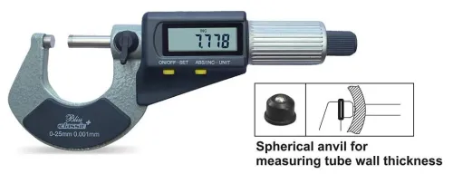
A point micrometer for machinery must specify graduation, point radius or included angle, contact material, ratchet or friction thimble, and replaceable points.
For brake-disc thickness, a general caliper can bridge a wear lip, dirt or a local defect; use a micrometer with suitable disc contacts or a defined multi-point method when minimum thickness or thickness variation controls acceptance.
Use the correct technique for reliable readings
Clean the part and instrument before measuring. Remove oil, chips and burrs from the contact surfaces, then let both the tool and part reach the same room temperature; thermal differences can alter a close automotive tolerance.
1. Inspect the point micrometer’s pointed anvil and spindle for damage. Close them gently with the ratchet, not by forcing the thimble, and confirm the zero reading. Place the points in the groove or root, keep the spindle aligned with the feature, and rock the micrometer slightly to find the minimum stable reading.
2. Wipe the dial caliper’s beam, jaws and depth rod. Close the jaws lightly, check that they meet without a gap, and set or confirm zero in the same orientation used for the part. A clean zero does not prove accuracy, so verify it with calibrated gauge blocks or setting standards.
3. For an outside diameter or thickness, seat the caliper jaws squarely and use only enough pressure to remove clearance. Excess force spreads the jaws and produces a false small reading; angled jaws produce a false large one.
4. Read the dial straight on, hold the caliper steady, and repeat the measurement at several positions around a shaft or rotor. Record the spread, not just the first value.
For dial calipers in jaipur or elsewhere, treat the 0.02 mm dial increment as resolution, not accuracy. Check the specified indication error, repeatability and jaw condition in the calibration record.
Recognise surfaces and dimensions that need another tool
A reading becomes unreliable when the contact lands on a burr, wear lip, casting peak, or inaccessible surface instead of the defined measuring feature. A point micrometer for machinery reaches narrow grooves, keyways and spline roots, but its pointed contacts can mark soft metal and give unstable results on rough castings.
| Feature | Why either tool fails | Better choice |
|---|---|---|
| Rough casting or pitted shaft | Contacts sit on peaks and pits, producing variable readings | Clean and deburr the datum; use a comparator or CMM for a defined profile |
| Brake-disc thickness with a wear lip | A dial caliper can bridge the lip and report too much material | Use a disc micrometer, or measure at defined points with a suitable micrometer |
| Hot steel component | Thermal expansion shifts the dimension before instrument error is counted | Cool the part and tool to 20 °C; use ISO 1 as the reference |
| Internal crack, porosity or inclusion | Neither tool detects material below the surface | Use dye penetrant, magnetic-particle, ultrasonic or radiographic testing as applicable |
| Deep bore, hidden step or complex contour | Jaws or pointed contacts cannot establish the required datum | Use an inside micrometer, bore gauge, depth micrometer, blade micrometer or CMM |
A dial caliper for automotive parts is adequate for accessible, clean dimensions, not concealed geometry. A 100 mm steel part can shift roughly 11–12 micrometres across a 10 °C temperature difference, so do not accept a borderline result from a hot component.
Specify and source an inspection tool in Jaipur
A point micrometer or dial caliper in Jaipur should be selected from the feature and its tolerance, not from price or advertised resolution. Use pointed contacts for a groove root, narrow web, keyway, or other recessed thickness; use a dial caliper for rapid checks of lengths, shoulders, outside and inside diameters, and steps.
For brake-disc minimum thickness, specify disc contacts or a defined multi-point method instead of allowing jaws to bridge a wear lip.
Before ordering, require these details in writing:
1. For a point micrometer, state metric or inch graduation, measuring range, spindle and anvil geometry, point radius or included angle, contact material, ratchet or friction thimble, and whether points are replaceable. For a dial caliper, state range, 0.02 mm or 0.001 in increment, permissible indication error, repeatability, and jaw parallelism. Resolution is not accuracy.
2. Request a calibration report tied to the instrument’s serial number. It should show calibration date, standards used, measured points, as-found and as-left results, stated error, and the next review date. A clean zero alone proves nothing; verify against calibrated gauge blocks or setting rings.
3. Confirm recalibration, jaw repair, replacement dial components, and batteries where applicable. Ask how the supplier records instrument history and handles a failed verification.
4. Compare local stock with that support. Yamayo Instruments can help you specify the geometry and documentation before you accept a tool. Ask sellers of dial calipers in Jaipur to demonstrate zero, smooth travel, jaw condition, and a repeat check on your automotive sample.
Related product
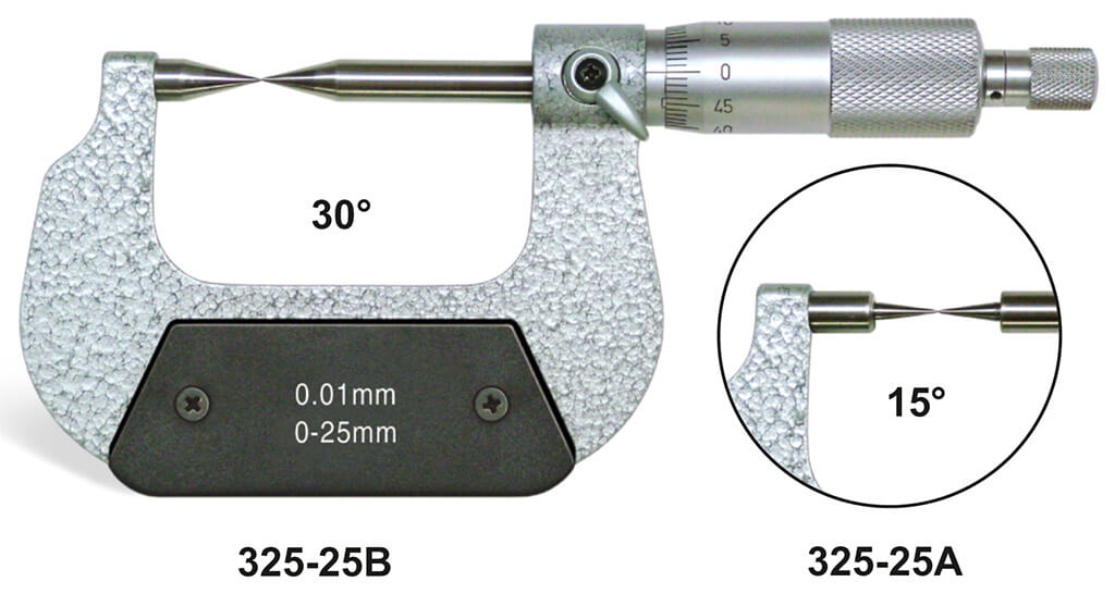 | Micrometers Point Outside Micrometers The Point Outside Micrometer is a specialized precision measuring instrument designed for measuring web thickness of... View product → |
Frequently asked questions
When should you use a point micrometer instead of a dial caliper?
Use a point micrometer when a narrow groove, root or recessed feature requires pointed contacts. Use a dial caliper for quick checks on accessible dimensions.
Which is faster for automotive parts inspection?
A dial caliper is faster for repeated checks because it opens quickly and displays the reading immediately. A point micrometer takes longer to position but controls contact on confined features.
How do you obtain reliable readings from either instrument?
Clean the part and contacts, align the instrument square to the feature, apply consistent measuring force, and repeat the reading to confirm it.
When is neither a point micrometer nor a dial caliper suitable?
Use another tool for threads, rough or soft surfaces, curved contact areas, very tight tolerances, or dimensions that require a specialised depth, thread or radius gauge.