A pointed outside micrometer can reach narrow tooth spaces, but its reading is meaningful only when the contact points, measuring plane, force, and gear geometry are defined. You will be able to match each instrument to the dimension you need, inspect spur and helical gears correctly, and specify a calibrated purchase without confusing resolution with accuracy.
Key takeaways
- Match the instrument to tooth thickness, span measurement, or local feature size.
- A point micrometer does not automatically measure standard chordal tooth thickness.
- Use gear tooth vernier calipers for addendum and chordal tooth thickness checks.
- Specify gear type, module, pressure angle, range, resolution, and calibration needs.
Which instrument matches the gear dimension you need?
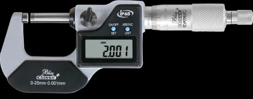
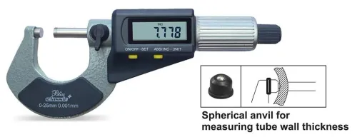
Choose the instrument by the dimension your drawing reports. A point outside micrometer suits a local measurement between narrow flanks, grooves, shoulders, or small-radius features; its pointed contacts do not automatically report standard chordal tooth thickness.
| Option | Reported dimension | Best fit |
|---|---|---|
| Point outside micrometer | Selected local thickness, clearance, or narrow-space dimension | A defined contact between flanks, near a groove, shoulder, or small radius |
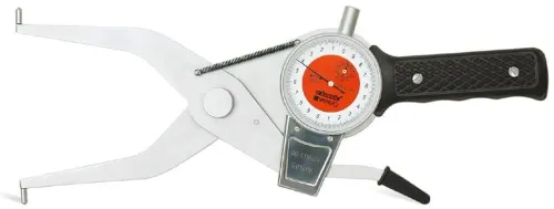
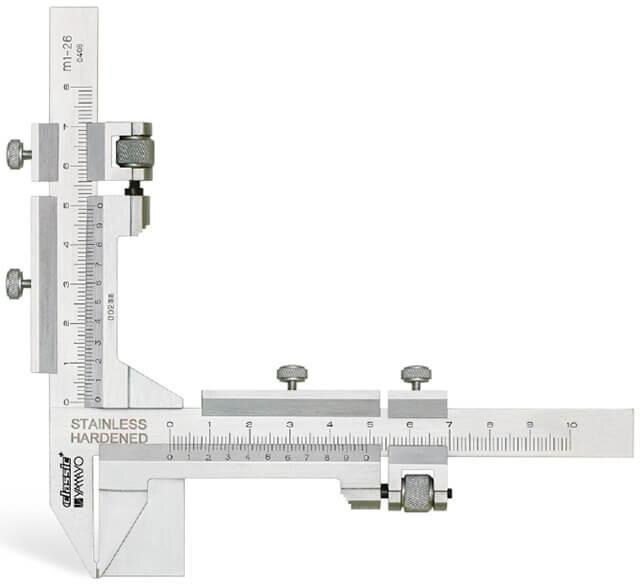
| Gear tooth vernier calipers | Chordal tooth thickness and chordal addendum or tooth depth | Set both slides from gear geometry before measuring |
| Digimatic gear tooth caliper | The same chordal thickness and depth readings, shown digitally | Faster reading and reduced scale-reading error |
| Disc micrometer | Root tangent length or another tangent dimension | Disc-shaped contacts reaching specified tangent points |
Set a gear tooth vernier caliper from tooth count, pitch radius, pressure angle, profile shift, and backlash allowance—not outside diameter alone. A digimatic gear tooth caliper changes the display, not the measurement principle.
Circular tooth thickness, base-tangent length, and root tangent length are different readings. Span measurement over several teeth and over-pin or over-ball measurement use different contact arrangements and average local errors more effectively than one pointed contact.
A point micrometer for machinery can verify a selected local dimension during repair, but it cannot establish involute profile error, helix deviation, pitch error, runout, backlash, or contact pattern. Choose a gear-measuring method when acceptance depends on those conditions.
Can a pointed outside micrometer measure tooth thickness reliably?
A pointed outside micrometer can measure tooth thickness reliably only when the drawing or inspection plan defines the exact contact locations. Seat each point on the intended tooth flanks, align the spindle square to the feature, and keep both contacts in the specified chordal or transverse plane.
- Do not place the points on the tooth tip, roll them into the involute, or let either point touch the tooth fillet. A burr, rounded tip, or fillet radius can dominate the reading.
- Treat tooth-tip thickness and root thickness as separate measurements, each with its own defined location.
- For tooth space, make sure the contacts reach both opposing flanks without bridging the wrong section.
- Keep the frame stable, use the friction device if supplied, and apply the same measuring force each time.
- Take repeated readings without rocking the instrument, then record the tooth number and angular location.
- State the gear datum, measurement plane, contact force, number of locations, burr condition, temperature, and reporting format in the inspection method.
A point micrometer for gear tooth inspection in Hyderabad is useful for a local flank or narrow-space check because its pointed contacts reach areas that flat anvils cannot. Its nominal range does not prove that the points reach the required geometry.
One reading is not a substitute for span, pin, ball, or gear-machine inspection when production acceptance depends on averaged or functional geometry. For machinery repair, a point micrometer verifies a selected local dimension; it does not establish involute error, helix deviation, pitch error, runout, or contact pattern.
How do you perform vernier gear tooth measurement?
Begin with the gear drawing or calculation sheet, not the outside diameter alone. For a standard spur gear, theoretical pitch-circle chordal thickness is 2r·sin(π/2z), where r is pitch radius and z is tooth count. Profile shift, backlash allowance, pressure angle, tooth modification, and helical geometry alter the setting.
For vernier gear tooth measurement, use this checklist:
- Set the tooth-depth slide to the specified chordal addendum.
- Set the tooth-thickness slide to the calculated or tabulated chordal value.
- Place the depth reference on the tooth tip, then seat the jaws on both flanks at the defined chordal section.
- Keep the jaws square, remove chips, avoid rocking, and apply the same light seating pressure to every reading.
- Measure several distributed tooth numbers and repeat any outlier.
- Record the tooth number, flank or measurement location, depth setting, reading, temperature, and burr condition.
Ordinary vernier caliper jaws do not follow involute flanks or narrow tooth spaces consistently. Jaw angle and seating point can therefore produce different readings on the same tooth. Gear tooth vernier calipers are purpose-built two-setting instruments; they are not ordinary calipers with modified jaws.
Check the instrument’s setting against the drawing before accepting results. A correct outside diameter cannot compensate for an incorrect chordal depth or tooth-thickness value.
What changes when you inspect spur and helical gears?
Spur gears offer easier access because their teeth run parallel to the gear axis, so the flank and measurement plane remain straightforward to reach. Define whether the inspection reports transverse-plane chordal tooth thickness, base-tangent length, root tangent length, or a span over a specified number of teeth.
1. For vernier gear tooth measurement on a spur gear, use the gear drawing to set the tooth-depth and tooth-thickness contacts. Record the tooth number, measurement plane, flank, contact direction, and specified span; do not assume an outside-diameter reading provides the correct setting.
2. A helical gear changes the apparent flank position and the path available to a jaw or pointed contact. Gear tooth vernier calipers can become awkward because their contacts do not naturally sit in the required normal or transverse plane. Specify the plane, flank, contact direction, helix-angle correction, and any depth correction before taking readings.
3. Do not copy a spur-gear depth setting onto a helical gear. A mispositioned contact can measure a different section of the involute and produce a repeatable but irrelevant value.
4. Treat tooth thickness and backlash as different results. Backlash depends on both mating gears, centre distance, operating position, and lubricant. If acceptance concerns functional meshing, use span measurement, over-pin or over-ball measurement, or a gear measuring machine instead of treating one local point reading as the complete result.
How should you specify and buy a gear measurement instrument in Hyderabad?
Give the supplier the module or diametral pitch, tooth count, pressure angle, helix angle, outside diameter, root geometry, measurement plane, target dimension, and tooth-space access. This lets a gear tooth measurement supplier in Hyderabad select contacts that physically reach the flanks rather than relying on nominal range alone.
| Check | What to compare |
|---|---|
| Usable range | Covers the target dimension and gear diameter |
| Graduation or resolution | 0.001 mm display; not proof of 1 µm accuracy |
| Maximum permissible error and repeatability | Confirms accuracy and consistency |
| Contact-tip radius and jaw or anvil geometry | Fits the flank, root, or narrow space without bridging |
| Measuring force | Prevents inconsistent deflection or seating |
| Spindle lock or friction device | Controls alignment and operator pressure |
| Spare contacts | Keeps the instrument serviceable after wear or damage |
Ask for calibration records naming the instrument serial number, range, resolution, measured deviations, standards, environmental conditions, and traceability. An ISO/IEC 17025-accredited calibration option is more informative than an unspecified certificate of conformity.
Before inspection, condition the gear and instrument near 20 °C. Steel changes roughly 11–12 µm per metre per °C, so warm hands, sunlight, and recently machined gears can shift readings.
For a point micrometer for gear tooth inspection in Hyderabad, request a written method stating contact points, force, tooth locations, burr condition, equilibration time, and reporting format. Yamayo Instruments can help match the stated gear geometry with dimensional-inspection equipment and calibration requirements.
Related products
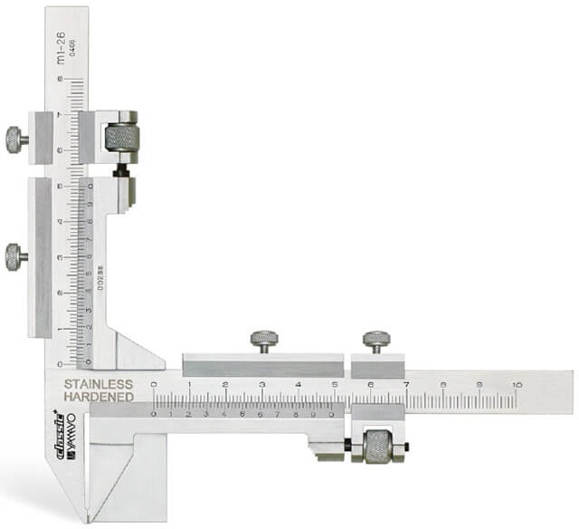 | Calipers Gear Tooth Vernier Calipers The Gear Tooth Vernier Caliper is a precision measuring instrument specially designed for accurate measurement of gear... View product → |
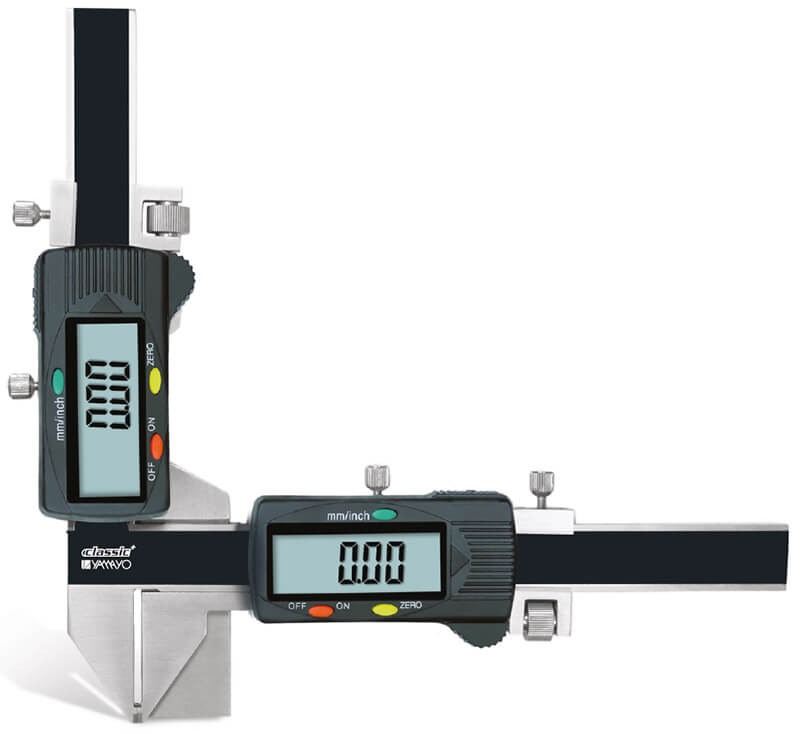 | Calipers Digimatic Gear Tooth Calipers The Digimatic Gear Tooth Caliper is a precision digital measuring instrument specifically designed for accurate... View product → |
Frequently asked questions
Which instrument matches the gear dimension you need?
Use a point micrometer for local measurements between narrow flanks, grooves, shoulders, or small-radius features. Choose gear tooth vernier calipers when the drawing requires addendum and chordal tooth thickness. Use a span micrometer or measuring-over-pins method when the specification calls for tooth span or functional size.
Can a pointed outside micrometer measure tooth thickness reliably?
It can measure a defined local distance when the pointed contacts seat consistently on the intended flanks. It does not directly provide standard chordal tooth thickness unless the contact geometry, reference location, and calculation match the drawing.
How do you perform vernier gear tooth measurement?
Set the vertical slide to the specified addendum, seat the horizontal jaws on the two tooth flanks, and read the chordal tooth thickness. Clean the gear, avoid forcing the jaws, repeat on multiple teeth, and record the tooth location and measurement direction.
What changes when you inspect spur and helical gears?
Spur gears present teeth across the face width, while helical gears introduce helix angle and axial position. For helical gears, specify the measurement plane, face position, helix direction, and whether the result is normal, transverse, or base-pitch related.
How should you specify and buy a gear measurement instrument in Hyderabad?
Give the supplier the gear type, module or diametral pitch, pressure angle, tooth count, outside diameter, face width, expected tooth-thickness range, resolution, accuracy, and calibration requirements. Ask for the instrument's measurement method, range, calibration certificate options, and service support.
Related product
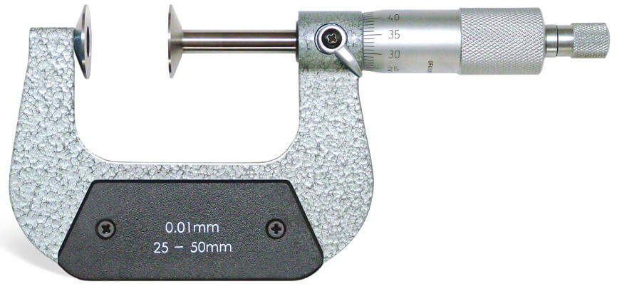 | Micrometers Disc Micrometers The Disc Micrometer is a specialized precision measuring instrument designed for measuring the root tangent length of spur gears,... View product → |