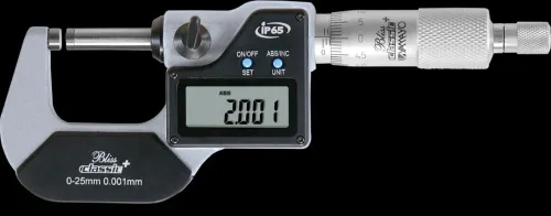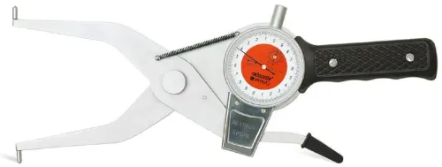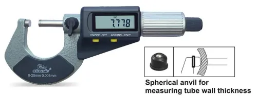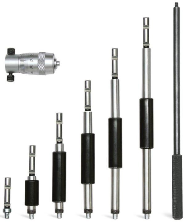
A rod-type inside micrometer can measure a bore, recess, or internal length, but it is not automatically the right instrument for measuring a screw thread’s pitch diameter. You will be able to identify the correct micrometer, select rods and extensions, verify the instrument, take a defensible reading, and specify what to ask a Hyderabad supplier before ordering.
Key takeaways
- Match rod length and extension range to the drawing’s bore depth.
- Rock the micrometer to find the true minimum bore reading.
- Check zero, calibration status, and suitability for your tolerance.
- Compare suppliers on traceability, accessories, and instrument availability.
Choose the right instrument for the measurement you call “screw measurement”
A rod-type inside micrometer measures the internal feature around a screw, not the screw thread itself. It measures a bore, counterbore, slot, or blind recess when you align the rod with the feature and rock it to locate the true minimum reading.
It does not determine pitch, flank angle, or the pitch diameter of an external thread.
| Instrument | What it measures | Use it when |
|---|---|---|
| Rod-type inside micrometer | Internal diameter, length, bore, or recess | The drawing controls the surrounding hole or internal seat |
| Thread micrometer | Comparative pitch diameter of an external thread | The screw’s pitch diameter is the required characteristic |
| Three-wire method or optical system | Derived pitch diameter, thread form, pitch, flank angle, or defects | Thread geometry needs calculation or detailed inspection |
A search for an inside micrometer rod type for screw measurement in Hyderabad must therefore start with the drawing feature, not the word “screw.” If the requirement is the thread itself, choose a screw measurement micrometer, three-wire setup, or vision system instead.
A rod-type instrument can give a misleadingly precise answer when its contact points sit on thread crests or chamfers rather than the specified bore. For an internal bore, clean the bore and anvils, insert the rod squarely, rock through the axis, and apply the ratchet or friction thimble consistently.
Select rods and extensions against the workpiece drawing
A rod that reaches the hole is not automatically suitable. Read the drawing for the minimum bore diameter, measured depth, shoulder location, recess width, and whether the feature is a through-bore or blind hole. Then confirm that the rod diameter, contact tip, and usable measuring depth fit without striking the shoulder.
Specify these points before requesting an inside micrometer rod type in Hyderabad:
- Target dimension and tolerance, such as 42.00 ±0.03 mm
- Required measuring range and rod increments
- Extension lengths needed to reach the bottom or reference face
- Metric or inch graduation, resolution, and display type
- Contact geometry for a flat bore, stepped bore, slot, or narrow recess
- Supplied setting standard and the size range it covers
Use the drawing to compare common configurations:
| Configuration | Check against the drawing | Disqualifying condition |
|---|---|---|
| Short rod | Minimum bore diameter and shallow depth | Rod or shoulder cannot enter squarely |
| Extension rod | Required depth plus clearance behind the bore | Extension bottoms out before the measuring faces contact |
| Small contact tip | Narrow recess or stepped feature | Tip touches a radius, chamfer, or thread instead of the measuring surface |
| Long assembly | Deep blind hole or separated reference faces | Flexure or poor handling compromises repeatability |
For a blind hole, record the bottom geometry and corner radius; a nominal range that includes the dimension proves nothing if the contact tip cannot seat on the intended surface. Ask a rod type micrometer supplier for a dimensional drawing showing rod diameter, extension length, shoulder clearance, and total reach.
Include the drawing number and revision with your purchase request.
Use the instrument without hiding bore variation
A reliable bore reading comes from controlled contact, square alignment, and repeated rocking—not from a single stationary reading. Clean the part and measuring contacts, then let both reach the same stable temperature; hand heat, chips, oil film, and burrs can shift the result.
1. Select a rod whose range covers the target dimension, including the required extension length and contact geometry. Confirm that the setting standard covers the assembled size.
2. Wipe the bore and anvils with a clean, lint-free cloth. Remove burrs without altering the edge, and check that no chip is trapped at the blind-hole bottom.
3. Insert the rod squarely to the measuring depth. Keep the instrument’s axis aligned with the bore; a tilted position creates cosine error.
4. Apply the same ratchet or friction-thimble force used for verification. Do not force the contacts against the wall, because excessive pressure can distort a thin component or produce a false size.
5. Rock the inside micrometer gently through the bore while maintaining contact. For a diameter, record the true minimum reading found during this sweep; for a recess length, locate both required contact points without letting the rod bind.
6. Repeat the measurement at several angular positions and depths. Variation between positions reveals taper, ovality, or a local defect that one reading would hide.
7. Recheck the instrument against its setting standard after the series. Record the individual readings, location, temperature, rod and extension used, and any deviation.
Inside micrometer availability does not establish suitability. A screw measurement micrometer or thread gauge remains necessary when pitch diameter, flank angle, or pitch—not the surrounding bore—is the measurement objective.
Verify zero, calibration, and measurement-system suitability
Check the instrument against a calibrated setting standard close to the workpiece size; a closed-thimble zero alone does not prove an inside micrometer is accurate.
1. Clean the anvils, rod ends, setting standard, and bore. Dirt can create a false high reading or prevent full contact.
2. Fit the selected rod and extension, then verify it against a certified setting ring, master bore, or calibrated internal standard. Record the indicated error at the size you will measure, not only at the smallest range point.
3. Insert the micrometer squarely and rock it through the bore to locate the true minimum reading. Repeat the check several times using the same ratchet or friction-thimble force; inconsistent readings indicate poor technique, loose connections, or damaged contact points.
4. Check the calibration certificate for the instrument’s stated accuracy, calibration points, traceability, and due date. Confirm that the certificate covers the assembled rod and extension combination.
5. Compare the total measurement uncertainty, including repeatability and operator variation, with the drawing tolerance. Accept the instrument only when that uncertainty is substantially smaller than the tolerance; your quality system sets the required ratio.
Resolution alone is not accuracy. Inside micrometer availability in Hyderabad does not establish suitability without the range, standard, calibration evidence, and complete rod assembly. For an inside micrometer rod type in Hyderabad, reject any set that cannot provide replacement rods, compatible extensions, or verification support for the size being controlled.
Specify supply requirements when comparing Hyderabad vendors
If you are asking for an inside micrometer rod type for screw measurement in Hyderabad, define the feature before comparing prices. A bore in a screw assembly is not the same as thread pitch diameter; the latter needs a screw thread micrometer or thread-gauging method. “Inside micrometer availability” alone does not prove suitability.
Put these requirements on the quotation:
- Measuring range, minimum bore or recess size, and required extension-rod lengths.
- Metric or inch graduation, resolution, display type, stated accuracy across the selected range, and repeatability.
- Contact geometry and rod material suited to the bore, slot, through-hole, or blind-hole application.
- Interchangeability of extension rods, rod increments, supplied setting standard, complete case, and spare contact parts.
- Calibration report identifying the instrument and extensions, calibration date, measurement points, reported error, uncertainty where applicable, and traceability to national or international measurement standards.
- Replacement-rod availability, delivery scope, recalibration support, and after-sales verification.
A generic certificate of conformity does not replace a calibration report. Ask the rod type micrometer supplier to confirm that every listed rod belongs to the quoted system, not merely that compatible parts exist in a catalogue.
Yamayo Instruments can be compared on this evidence rather than local stock alone: a complete, interchangeable set with documented accuracy remains usable when the original rod needs replacement or the inspection range changes.
Frequently asked questions
What does a rod-type inside micrometer measure around a screw?
It measures internal features such as a bore, counterbore, slot, or blind recess; it does not measure the screw thread itself.
How do you choose rods and extensions for a bore?
Use the workpiece drawing to match the required diameter range, bore depth, blind-end clearance, and extension length.
How do you prevent a rod-type micrometer from hiding bore variation?
Take readings at multiple depths and angular positions, then rock the instrument through the bore axis to locate the true minimum reading.
What should you verify before buying from a Hyderabad supplier?
Check zero condition, calibration documentation, traceability, included rods and extensions, measurement range, delivery status, and after-sales support.