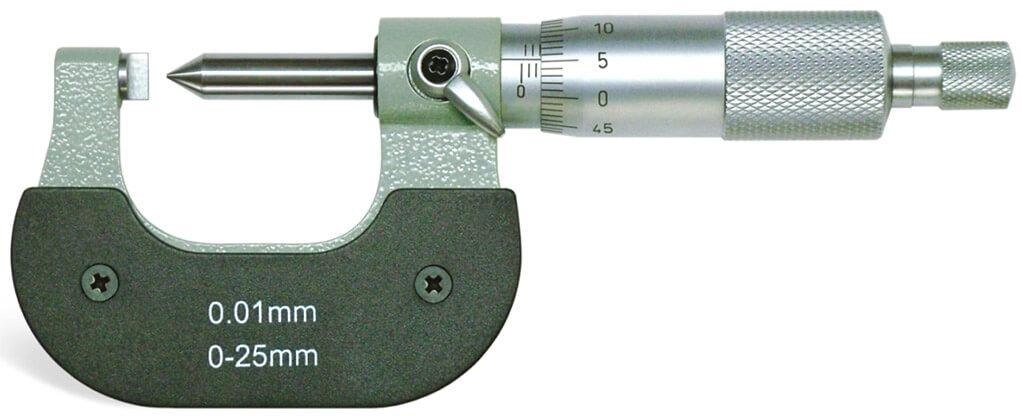
A point micrometer can enter a narrow groove or slot, but its pointed contacts do not automatically reproduce the measurement geometry of a terminal crimp. By the end, you will know where each instrument should contact, which terminal or component specification controls acceptance, and what to check before purchasing or using one in an automotive inspection process.
Key takeaways
- Match contact geometry to the terminal feature, not resolution alone.
- Measure crimp height at the terminal drawing’s specified location.
- Seat point contacts fully in grooves without forcing or tilting them.
- Specify range, tip shape, resolution, calibration, and local service support.
Which contact geometry matches the automotive feature?
For crimp height micrometers versus point micrometers in Hyderabad, match the contact geometry to the feature, not merely to the required resolution. A crimp height micrometer uses shaped contacts that seat or bridge the conductor-crimp barrel at the location defined by the terminal drawing.
A point micrometer uses a pointed or small-radius spindle and anvil to reach grooves, shoulders, slots, keyways, and drill webs.
| Feature | Crimp height micrometer | Point micrometer |
|---|---|---|
| Access | Fits the formed conductor-crimp barrel | Reaches restricted grooves, slots, shoulders, and webs |
| Contact geometry | Seats on intended crimp surfaces | Touches selected points with narrow tips |
| Repeatability | Consistent on the specified terminal section | Changes if tips move across wings, edges, or grooves |
| Accuracy | Verify traceability across the working range | Verify tip condition, range, and contact suitability |
A point micrometer is not an interchangeable substitute. Its tips can contact different parts of the crimp wings, enter a groove, or locally deflect thin terminal material, creating a systematic difference rather than a simple resolution difference. Use it for a defined narrow feature; use the dedicated instrument for a controlled crimp-height characteristic.
Crimp height is not crimp width, conductor compression, terminal position, pull-out strength, or electrical resistance. A compliant height does not prove wire-brush position, bellmouth, insulation support, strand condition, or mechanical performance. Use the terminal drawing and process specification, then apply pull-force testing or cross-section examination where required. This is the essential automotive micrometer comparison.
How do you measure a terminal’s crimp height correctly?
A correct crimp-height reading comes from the specified conductor-crimp section, not from the most convenient part of the terminal. Before measuring, identify the terminal family, wire gauge, conductor cross-section, crimp profile, and exact location shown on the terminal drawing or applicator specification.
| Terminal feature | Include in measurement | Exclude unless specified |
|---|---|---|
| Conductor-crimp barrel | Formed surfaces contacted by the crimp-height micrometer | Exposed strands |
| Insulation-support wings | None | Entire insulation-support area |
| Barrel details | Specified conductor-crimp section | Wire stop, bellmouth, seam, transition, deformed sections |
Confirm the terminal is clean and stable. Zero the instrument, clean the contact surfaces twice in succession, and repeat the check if the zero changes unexpectedly. Seat the crimp-height micrometer squarely across the finished conductor-crimp barrel, with its shaped contact faces engaging the intended formed surfaces rather than insulation or exposed strands.
Close it with the ratchet or friction device using the same controlled action every time; do not force the spindle.
A reading near a bellmouth, wire stop, seam, or crimp transition can differ materially from one taken at the specified section. Comparing those locations can falsely suggest instrument drift. This point matters in any automotive micrometer comparison, including when evaluating crimp height micrometers in Hyderabad.
Record the measured value, exact location, wire identification, and permitted tolerance from the specification. Crimp height alone does not confirm strand position, bellmouth, insulation support, pull-out strength, or electrical performance.
How should a point micrometer enter a groove, slot, or drill web?
A point micrometer is physically suitable only when its tips can reach the intended opposing surfaces without touching an edge or excluded surface. Check these dimensions before you place it:
- Groove width and depth
- Slot width, depth, and approach angle
- Drill diameter and web geometry
- Shoulder location
- Tip shape, radius, reach, and measuring range
The pointed spindle and anvil must enter the feature without riding onto an edge, contacting a chamfer, or touching the bottom when the drawing excludes it. Align the spindle with the measurement direction and keep the frame square to the part.
Tilting changes the contact point and can make a narrow slot read wider or narrower. Apply the ratchet or friction device consistently; excessive force can deflect thin terminal material.
For an automotive micrometer comparison, use the feature and its specification—not access alone—as the decision rule.
| Option | Correct seating | Main risk |
|---|---|---|
| Point micrometer | Tips seat on the specified groove, slot, shoulder, or web surfaces | Wedging, edge contact, or false readings from tilt |
| Drill-web measurement | Both tips contact the web surfaces | One tip lands on an adjacent bore wall |
| Keyway or groove | Tip radius fits without wedging | The tip contacts a chamfer or excluded bottom surface |
A point micrometer can suit selected connector or terminal dimensions. Choose it only after the component drawing defines the feature, measurement direction, and tolerance.
What should you specify when buying in Hyderabad?
Choose the instrument by feature geometry and acceptance specification, not by asking for a generic digital micrometer. Buyers comparing digital micrometers in Hyderabad should provide:
- Terminal or component family and the exact conductor-crimp location, or the feature geometry to measure
- Metric or inch units, working range, required resolution, and maximum permissible error
- Contact shape and calibration requirement
- For terminals: crimp profile, wire gauge, insulation-support arrangement, and the manufacturer’s crimp specification
- For machined parts: point angle or radius, tip reach, groove width, slot depth, drill-web geometry, and access angle
| Option | Specify | Main selection risk |
|---|---|---|
| Crimp height micrometer | Anvil form, crimp profile, wire gauge, and specified barrel location | A mismatched contact can touch insulation, strands, or a crimp transition |
| Point micrometer | Tip angle or radius, reach, feature width and depth, and approach angle | A tip can ride an edge, wedge in a groove, or contact the wrong surface |
For crimp height micrometers in Hyderabad, allow the instrument and small steel terminals to reach the inspection area’s temperature. Avoid warming the frame by gripping it; use the ratchet or friction device consistently.
Digital indication reduces reading and parallax errors or supports data output, but it cannot correct poor alignment, thermal effects, worn tips, inconsistent force, or unsuitable geometry.
ISO 3611 addresses external micrometer construction and verification, not terminal-specific suitability. Ask for a calibration report naming the instrument, range, resolution, uncertainty or error result, and traceability. Yamayo Instruments can help compare these specifications when selecting a point micrometer or crimp instrument.
Related products
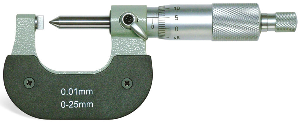 | Micrometers Crimp Height Micrometers The Crimp Height Micrometer is a specialized precision measuring instrument designed for accurate measurement of crimp... View product → |
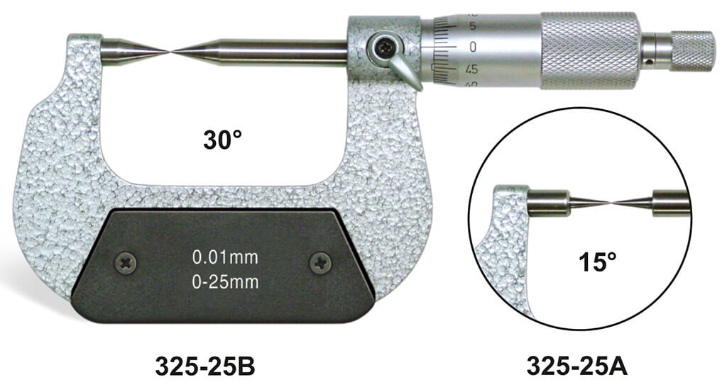 | Micrometers Point Outside Micrometers The Point Outside Micrometer is a specialized precision measuring instrument designed for measuring web thickness of... View product → |
What inspection sequence controls errors and proves the result?
Release a reading only after the instrument, part condition, and measurement method agree. For crimp height micrometers versus point micrometers in Hyderabad, use this sequence:
- Clean the terminal or component and both contact surfaces.
- Inspect the tips for wear, damage, or contamination, then verify zero.
- Check the instrument across its working range with dimensional standards or a validated master matching the measurement geometry.
- Place the part at the specified drawing location, keep the instrument aligned, apply the ratchet consistently, and repeat readings without shifting to another section.
- Reject or segregate terminals with crushed wings, cut strands, damaged insulation support, or visible deformation.
| Instrument | Verification focus | Release limitation |
|---|---|---|
| Crimp-height micrometer | Master representing the crimp profile and location | Height alone does not prove strand position or contact |
| Point micrometer | Standard or master matching tip access and feature geometry | Tip position can alter readings in grooves, slots, or thin material |
| Either instrument | Zero, range, tips, alignment, and repeatability | Closure zero cannot reveal seating, spindle, or range errors |
For crimp height micrometers in Hyderabad, compare the result with the terminal or component drawing, including its permitted value and tolerance. Never create an acceptance limit from resolution. Record instrument identification, calibration status, operator, location, part number, wire or component details, measurement location, and result.
Use crimp-height checks for frequent non-destructive control. Add pull-force testing and destructive cross-section examination when the process-control plan requires evidence of internal strand deformation and contact.
Frequently asked questions
Which contact geometry matches an automotive feature?
Use shaped crimp-height contacts for conductor or insulation barrels. Use pointed contacts for narrow grooves, slots, drill webs, and recessed features.
How do you measure a terminal’s crimp height correctly?
Follow the terminal drawing for the measurement location, clean the contacts and terminal, align the micrometer squarely, and record the reading with the terminal and tool identification.
How should a point micrometer enter a groove, slot, or drill web?
Insert the pointed contacts along the feature’s centreline, seat them on the intended surfaces, and avoid forcing the tips or allowing the tool to tilt.
What should you specify when buying in Hyderabad?
Specify measuring range, resolution, contact shape, tip angle or radius, display type, calibration documentation, and access to local support and replacement parts.
What inspection sequence controls errors and proves the result?
Confirm the drawing revision, identify the terminal and sample, inspect and clean the feature, verify the micrometer, take repeat readings, and record the instrument ID and result.
Related products
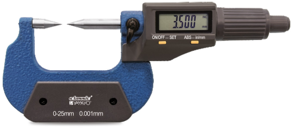 | Micrometers Digimatic Point Outside Micrometer Digimatic Point Outside Micrometer The Digimatic Point Outside Micrometer is a high-precision digital measuring instrument specifically designed for... View product → |
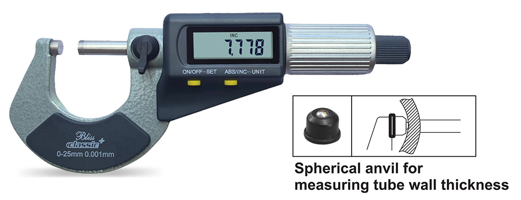 | Micrometers Digimatic Micrometers The Digimatic Micrometer is a high-precision digital measuring instrument designed for accurate external dimension measurement... View product → |
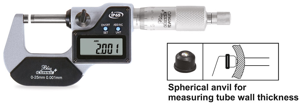 | Micrometers Digimatic Outside Micrometers The Digimatic Outside Micrometer is a high-precision digital measuring instrument designed for accurate external... View product → |