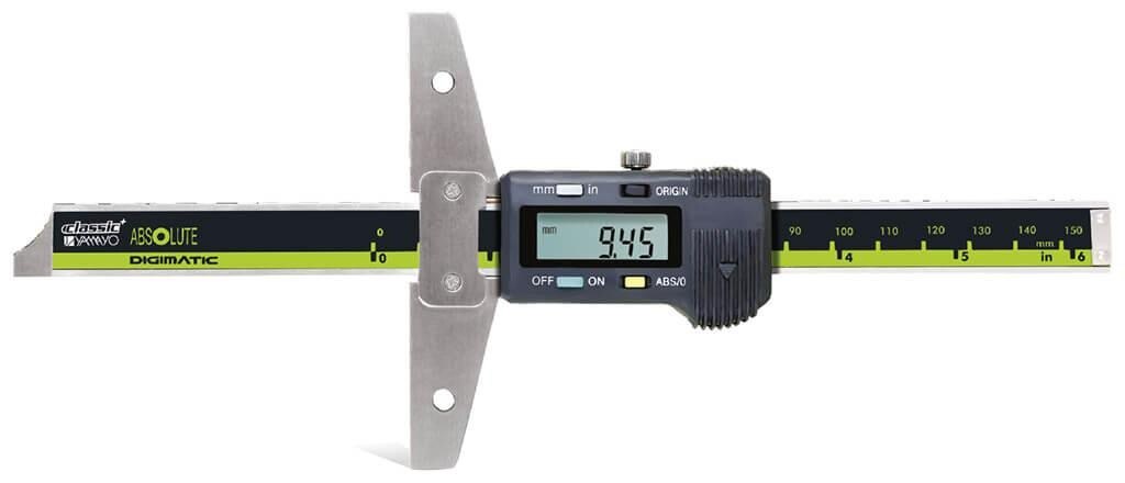
A suitable digital depth micrometer depends on more than the maximum depth printed on its box. Match the instrument to the feature geometry, datum surface, tolerance, access constraints, measuring force, and verification method before you compare models or prices.
Key takeaways
- Start with the feature, datum surface, and drawing tolerance.
- Match resolution and accuracy to the required measurement tolerance.
- Choose the base and contact geometry for the feature shape.
- Verify zero, reference surfaces, and readings before approving the instrument.
Start with the Feature, Datum, and Tolerance
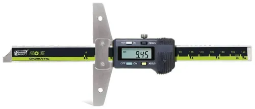
Start with the feature being measured, its datum surface, and the drawing tolerance. A digital depth micrometer measures from its reference base to the bottom of a hole, slot, recess, or shoulder, so identify exactly where the base must land and where the contact point must touch.
Record these details before comparing digital depth micrometer options for industrial measurement:
- Feature geometry: hole diameter, slot width, recess shape, shoulder location, and available clearance around the opening.
- Datum condition: flatness, length and width of the landing surface, and whether bosses or nearby walls could force the base to tilt.
- Surface condition: burrs, chips, paint, weld spatter, or other material that could hold the base away from the datum.
- Required depth: minimum and maximum depth, plus whether one instrument’s travel covers it or interchangeable rods are needed.
- Drawing tolerance: nominal depth and upper and lower limits, not just the number of decimal places shown.
- Required resolution: specify it separately from accuracy, repeatability, and accuracy variation across the measuring range.
A wide base can sit securely on a broad flat datum; a narrow base can enter confined areas but is easier to rock. If the tolerance is tight, compare the instrument’s maximum permissible error and repeatability with the allowed variation, because a 0.001 mm display does not guarantee 0.001 mm accuracy.
For a depth micrometer for quality control, also define whether SPC, wired, or wireless output is required, then confirm interface compatibility, inch or decimal format, trigger operation, instrument ID, and measurement timestamp.
Compare Bases, Rod Systems, and Digital Depth Micrometer Sizes
Choose the base and contact system around the opening before choosing the measuring range. A wide base gives better seating on broad, clean surfaces; a narrow base reaches close to shoulders and slots but rocks more easily. Interchangeable-base models let you change that trade-off for different parts.
Digital depth micrometer types differ in speed and flexibility:
| Type | Main advantage | Best fit |
|---|---|---|
| Interchangeable-rod | Covers several ranges with one instrument | Mixed depths and planned inspection work |
| Fixed-range rod | Faster setup with fewer rod-change errors | Repeated parts within one depth band |
| Blade-type | Enters narrow slots and restricted gaps | Keyways, thin recesses, and small openings |
| Interchangeable-base | Adapts seating width to the part | Components with varied datum surfaces |
Check the physical clearance around the feature, not only its depth. A rod that reaches the bottom can still fail if its diameter contacts a sidewall, the base cannot sit flat, or the contact point is hidden from the operator.
Common digital depth micrometer sizes are 0–25 mm, 25–50 mm, and 50–75 mm, followed by successive 25 mm ranges. Interchangeable-rod sets often extend to about 150 mm or 300 mm. Confirm whether the quoted range belongs to one instrument’s travel or the total coverage of several rods.
A long rod also increases deflection risk. For a very deep, tiny, or obstructed feature, compare a bore gauge, depth gauge, height-gage setup, or purpose-built probe before accepting a nominally suitable micrometer.
Match Resolution and Accuracy to the Drawing Tolerance
A 0.001 mm display does not make a depth micrometer accurate to 0.001 mm. Resolution is the smallest displayed increment; accuracy is closeness to the true depth, repeatability is the spread from repeated readings, and measurement uncertainty is the combined doubt from the instrument, setup, part, and method.
Match the specification to the drawing tolerance, not to the attractive display resolution. If a depth has a 0.020 mm total tolerance, an instrument with a large maximum permissible error can consume most of that allowance before you account for repeatability and setup.
Ask for maximum permissible error, repeatability, and accuracy variation across the measuring range—not just “0.001 mm resolution” or “0.00005 in resolution.”
Use this checklist when comparing digital micrometers:
- Confirm the stated accuracy at the depth you will measure; a specification valid near the zero position may not cover the full rod range.
- Include base seating in the uncertainty budget. Burrs, chips, paint, weld spatter, or a rocking base can create more error than the display increment.
- Repeat the measurement without repositioning, then remove and reseat the base. A tight first result with a wide reseated spread is poor repeatability.
- Choose a depth micrometer for quality control when controlled force and repeatable limited-range measurements matter more than a depth caliper’s speed and broader feature access.
- Reject the instrument when its stated accuracy plus repeatability and estimated setup uncertainty cannot distinguish an acceptable part from the drawing limits.
Choose the Contact Geometry and Build for the Work Environment
A spherical or rounded rod tip is not interchangeable with a flat tip in a blind hole. A drill point, radius, counterbore, or chamfer can change where the contact seats, so match the tip to the drawing’s specified datum and contact location.
| Feature or condition | Suitable choice | Check before purchase |
|---|---|---|
| Slot or narrow recess | Blade-type model or thin anvil | Minimum slot width, blade thickness, and contact stability |
| Blind hole with defined bottom | Rounded or flat rod tip matched to the datum | Contact diameter and seating method |
| Broad, clean surface | Stable flat base with a conventional rod | Base coverage and resistance to rocking |
| Coolant, washdown, or chips | Sealed digital micrometer with a stated IP rating | Button seals, battery-compartment design, and cutting-fluid compatibility |
| Electronic inspection records | Instrument with a compatible data-output port, cable, or wireless interface | Software protocol, connector, and data-capture workflow |
Blade arrangements reach confined features that a round rod may touch at the sidewall first, but they are less stable on broad surfaces. Confirm the manufacturer’s minimum access dimensions rather than relying on the nominal range.
IP ratings describe defined dust and water tests, not resistance to every coolant or cleaning chemical. For digital depth micrometer types, choose interchangeable-rod models for varied work and fixed-range models when quick, error-resistant deployment matters. A data-output feature is valuable only if it feeds your inspection record; otherwise transcription remains a failure point.
Long rods, tiny openings, or hidden contacts favour a bore gauge, height-gage setup, or dedicated probe over digital micrometers.
Verify the Reading Before You Approve the Instrument
Set the base fully on a clean, stable datum surface before measuring. Remove chips, burrs, paint and weld spatter; a rocking base can create more error than a 0.001 mm display. This is the practical check to make when comparing digital depth micrometer options for industrial measurement, including those from Yamayo Instruments.
- Zero the instrument on its reference condition, then confirm the reading at or near the actual working depth. Zero proves the electronics and contact condition; it does not prove accuracy at 100 mm.
- Extend the rod or blade without forcing it, seat the tip at the feature’s lowest point, and keep the base flat. Do not tilt the tool to find a reading.
- Lift and reseat the instrument at least three times at the same location. Record the spread between readings and investigate movement caused by rocking, poor access or an uneven bottom.
- Verify the range with traceable depth standards, gauge blocks in a suitable fixture, or a calibrated comparator arrangement. For a depth micrometer for quality control, also confirm the data output records the correct instrument ID, unit format and measurement time.
Choose another method when the base cannot sit flat, the bottom is curved or inaccessible, or the required uncertainty exceeds the micrometer’s repeatability and maximum permissible error.
| Method | Main limitation | Choose it when |
|---|---|---|
| Digital depth micrometer | Needs stable datum contact | The feature accepts its base |
| Depth gauge or height gauge | Slower setup | You need a controlled surface-plate reference |
| CMM or probe system | Higher programming and setup effort | Geometry, access or uncertainty defeats hand measurement |
Frequently asked questions
What should you identify before choosing a digital depth micrometer?
Identify the feature, datum surface, required base location, contact point, and drawing tolerance before comparing instruments.
How do digital depth micrometer sizes and rod systems affect selection?
Choose a size and rod system that cover the required depth while allowing the base to sit securely on the datum.
How should resolution and accuracy relate to the drawing tolerance?
Select resolution and accuracy that support the drawing tolerance rather than choosing based on display resolution alone.
Which contact geometry suits a depth measurement?
Match the contact point to the feature, such as a hole, slot, recess, or shoulder, and choose a base suited to the work surface.
How do you verify a digital depth micrometer before approval?
Check the zero setting, reference surfaces, contact condition, and readings against a known reference before approving the instrument.