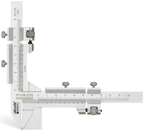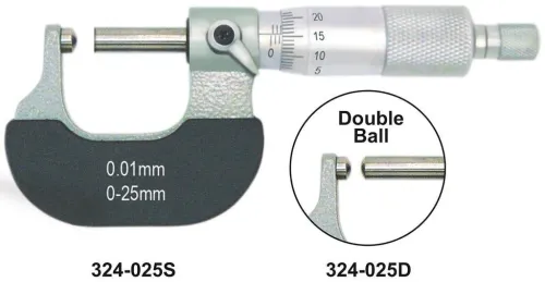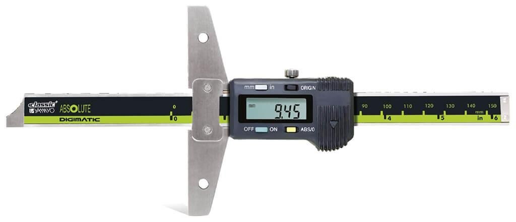
Brake-disc recesses, bearing seats and machined shoulders do not all present the same datum or access problem. By matching the base, contact geometry, capacity and documented accuracy to the feature, you can choose digital depth calipers that produce defensible readings instead of merely displaying fine increments.
Key takeaways
- Measure from a stable, genuine datum rather than a nominal feature.
- Choose base width and contact geometry for the opening and access path.
- Set capacity, resolution and accuracy against the required measurement tolerance.
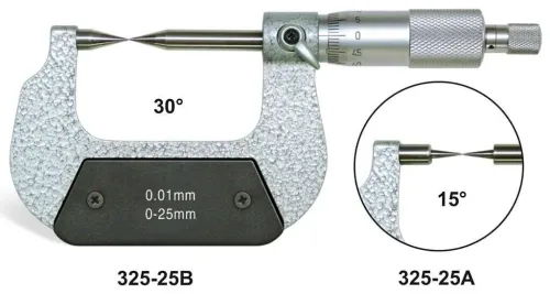
- Use a point micrometer when a caliper base cannot seat reliably.
Match the caliper to the automotive feature and datum
Use a digital depth caliper for automotive measurement when its base sits without rocking on a genuine datum and the required tolerance fits the instrument’s stated accuracy. The instrument measures from the surface beneath its base, not from the part’s nominal feature. A base bridging an opening can therefore measure from an unintended plane.
| Automotive feature | Suitable contact arrangement | Supporting datum |
|---|---|---|
| Brake-disc or drum recess | Flat base with blade or rod | Machined face surrounding the recess |
| Cylinder-head step or bearing seat | Flat or narrow base | Clean machined shoulder |
| Oil-pan surface or flange shoulder | Wide base, if the sheet or flange is rigid | Broad, undistorted surface |
| Casting pocket | Narrow base or suitable bridge | Flat land, not a rib or uneven casting |
| Keyway, small-radius groove or narrow hole | Point contact or another gauge | Defined groove or hole bottom |
A depth caliper for automotive work becomes unreliable when its base cannot seat, its rod touches a curved bore edge, or a blade contacts one side of a point-to-point keyway. Before comparing brands or display digits, inspect the opening, available seating area, required depth and tolerance.
A 0.01 mm display does not prove 0.01 mm accuracy. Choose a different contact or gauge when the datum is too narrow, curved, tapered or irregular.
Choose the base width and contact geometry for access
A wide, flat base gives the steadiest contact on machined cylinder-head faces, flange shoulders and bearing seats; a narrow base reaches restricted areas around a cylinder head, keyway or flange but rocks more easily on curved castings.
| Option | Best contact | Main risk |
|---|---|---|
| Wide flat base | Machined faces and broad recesses | Cannot enter a confined recess |
| Narrow base | Restricted steps, keyways and flanges | Rocks on a curved or uneven datum |
| Bridge-style base | Wide, uninterrupted surfaces | Falsely spans a hole, step or casting void |
Use a bridge-style base only when both feet rest on the same continuous plane. If it spans an opening or local step, the reading comes from an imaginary plane rather than the feature datum.
Match the projecting contact to the opening:
- Choose a flat blade for slots, channels and relatively wide grooves.
- Choose a round rod for an isolated hole or point.
- Choose a narrow blade where surrounding walls limit entry.
A rod touching a curved or angled bore can slide to an edge and report a false depth. That is one reason digimatic depth caliper types must be selected by access geometry, not by digital display or range alone.
Use a pointed contact for narrow holes, V-grooves and keyways. Point micrometer depth measurement can find a local low point, but a sharp point can mark a soft coating; specify the intended contact location and surface condition.
Put point angle, contact radius, base length, underside clearance and replacement-contact availability in the specification. They are measurement requirements, not afterthought accessories.
Set capacity, resolution and accuracy before you buy
Choose a usable depth range that reaches the feature bottom while leaving enough blade or rod engaged for stable contact. A long-range model is not automatically better: near-full extension increases bending, angular error and loss of contact.
| Option | Compare | Buying implication |
|---|---|---|
| Shorter range | More engagement at common depths | Prefer when it covers the complete feature |
| Longer range | Reaches deeper features | Reject if routine readings use the rod near full extension |
| 0.01 mm display | Shows finer increments | Accept a 0.02 mm tolerance only when documented accuracy, maximum permissible error, repeatability, calibration condition and method support it |
A 0.01 mm display does not make a 0.02 mm decision reliable. Verify the instrument against a gauge block or calibrated setting standard, and require calibration documentation that identifies the measurement condition and result.
For close comparisons, let the part, caliper and standard stabilise near 20 °C, the reference temperature specified by ISO 1; a hot brake component or a part fresh from machining or washing can differ through thermal expansion.
Specify coolant, oil, brake dust, chips and washdown exposure alongside sealed controls and an IP rating. Request data output if readings enter a quality system. Protection improves survivability, not cleanliness: wipe the base and contact, dry the instrument, and never store it wet.
These checks matter across digital depth calipers because environmental sealing cannot correct contamination, unstable temperature or poor repeatability.
Control the setup so the reading represents the real depth
A correct depth reading starts with a clean, stable datum and a contact that reaches the true feature bottom. Remove chips, dirt, loose sealant, paint flakes and corrosion without altering the production surface, then wipe the caliper base and blade or rod.
1. Zero the caliper with its base and contact arranged as they will be on the part. Zeroing on an unrelated bench surface can hide an orientation or seating error.
2. Seat the base fully against the datum and rock it lightly. Any rocking indicates debris, a raised area or an unsuitable base; do not accept the reading until the support is stable.
3. Hold the blade or rod normal to both the datum and feature bottom. An angled contact creates cosine error: the caliper reports the shorter projected distance, not the true depth.
4. Repeat the measurement after rotating the tool or changing its approach direction. A changing result points to setup or geometry error, not extra resolution that the display can solve.
5. Inspect the contact area for burrs, raised casting ribs, tapered or angled bores, curved surfaces and flexible oil-pan sheet metal. A rod can slide to an edge, while a base bridging an opening measures from an unintended plane.
6. Use a datum fixture, bridge arrangement or different gauge when the reference face is uneven or inaccessible. Do not force the caliper into position.
After a drop, crash or unexplained shift, check the instrument against a known reference or calibrated setting standard before measuring production parts. Stop using it if the result falls outside its documented accuracy.
Write a purchase specification—and know when to choose another gauge
Specify the feature and tolerance before comparing suppliers: a digital depth caliper for automotive work suits broad, stable datums and moderate tolerances, not every recessed feature.
Ask each supplier to state:
- Complete depth range, resolution, accuracy or maximum permissible error, repeatability, access depth, base width, base length and underside clearance.
- Contact form and point angle: flat blade, narrow blade, round rod or pointed contact.
- Resistance to oil, coolant, brake dust, chips and washdown; request the stated IP rating rather than “sealed” wording.
- Data output, calibration certificate, calibration condition, and availability of replacement blades, rods and points.
A 0.01 mm display does not support a 0.02 mm acceptance decision unless documented accuracy, calibration and the measurement method support it. Test candidate models on representative brake, cylinder-head, bearing, keyway and oil-pan parts; catalogue photographs cannot show rocking, restricted access or contact slip.
| Gauge choice | Best fit | Reject it when |
|---|---|---|
| Digital depth caliper | Broad datum with moderate tolerance | The base bridges a hole or cannot sit flat |
| Point micrometer depth measurement | Narrow hole, V-groove or defined contact location | A broad surface needs faster coverage |
| Fixture or specialised bore gauge | Inaccessible, tapered or highly irregular datum | The feature accepts a stable caliper base |
Ask Yamayo Instruments’ measurement specialists to confirm stated accuracy, base dimensions, contact options, calibration documents and replacement-contact support against your inspection plan. Choose the feature and tolerance—not “Digimatic” or the number of display digits.
Related products
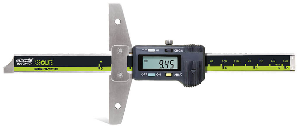 | Calipers Digimatic Depth CalipersCalipers Digimatic Depth Calipers The Digimatic Depth Caliper is a precision digital measuring instrument designed for accurate depth measurement of holes,... View product → |
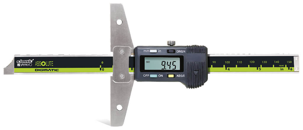 | Depth Measurements Digimatic Depth Calipers The Digimatic Depth Caliper is a precision digital measuring instrument designed for accurate depth measurement of slots,... View product → |
Frequently asked questions
How do you match a digital depth caliper to an automotive feature?
Identify the actual datum beneath the base and select the contact geometry for the hole, recess, step or groove being measured.
What base width and contact geometry should you choose?
Choose a base that bridges the feature without rocking and contacts surrounding material without obstructing access or touching unintended surfaces.
How do capacity, resolution and accuracy affect caliper selection?
Set the measurement range above the maximum depth, choose resolution finer than the required reporting increment, and confirm stated accuracy supports the tolerance.
When should you use another gauge instead of a digital depth caliper?
Choose a point micrometer depth measurement setup when the caliper base cannot reach a stable datum or its bridge geometry distorts the result.