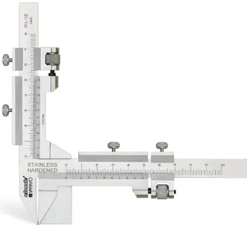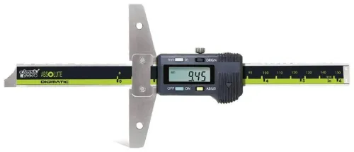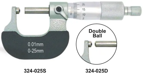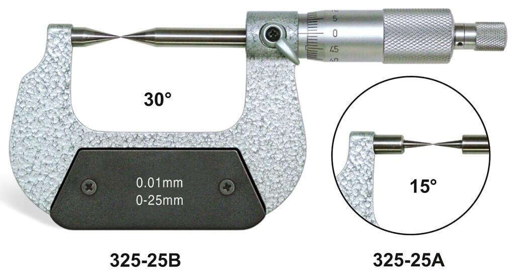
A pointed micrometer contact can produce changing height readings even when the digital display, beam, and carriage appear to work correctly. You will learn how to establish a repeatable datum, isolate contact-tool errors from gauge errors, and decide when another probe or measurement method is safer.
Key takeaways
- Keep the tip aligned with the same feature point on every measurement.
- Clean the surface plate, gauge base, workpiece, and contact before testing.
- Compare repeatability with a flat contact to isolate gauge faults.
- Use ball, knife-edge, or disc contacts to match the feature geometry.
Why a Point Micrometer Gives Unstable Height Readings
A point micrometer produces different readings because its tip may not contact the same geometric point twice. A tiny lateral shift can move the point from the nominal feature onto an edge, burr, chamfer, or radius, changing the measured height substantially.
The tip can also rock instead of seating firmly, especially on a narrow groove or uneven surface.
Point micrometer problems with single beam height gauge use are also force-sensitive. A pointed contact has very little contact area, so pressing harder can deflect the workpiece, shift the carriage, or push the tip past the intended contact. Dragging the point across the surface worsens the variation.
Approach from the same direction and use the ratchet or friction device specified for the micrometer.
Point micrometer height measurement does not automatically give the feature’s height above the surface plate. It measures the local distance between its contact points; the lower point must establish a repeatable datum, and both points must align with the intended height direction.
A single-beam gauge can add carriage slip or beam deflection, with the error changing at different heights or loads. Zeroing removes a constant offset, not these effects. Repeat the check at several lateral contact positions and at low, middle, and high carriage heights.
Consistent variation across positions indicates the contact or feature; variation with carriage height points toward the gauge.
A Controlled Setup for Point Micrometer Height Measurement
A reliable reading begins with the reference plane, not the gauge display. Clean the surface plate, gauge base, and workpiece datum; remove oil, chips, and raised burrs. A trapped particle or damaged plate area becomes a height error. Deburr the feature without changing its intended edge or step.
1. Place the workpiece firmly on the cleaned reference plane. Prevent rocking with the smallest practical support, and keep the datum surface fully seated.
2. Position the gauge base beside the feature, then confirm that the base is seated before moving or zeroing the gauge. Set the gauge against a certified reference height or zero it on the defined datum.
3. Adjust the point micrometer so its lower contact establishes the reproducible datum and its upper pointed contact approaches the intended feature. Do not use an edge, chamfer, radius, or burr as the contact unless that geometry is the feature being specified.
4. Align the pointed contact with the height direction. A tilted point introduces cosine error: the indicated displacement is approximately L cos θ, not the true displacement L.
5. Approach from the same direction each time, without dragging the point across the surface. Use the specified ratchet or friction device, because a small contact area makes force changes visible in the reading.
6. Record readings at several lateral positions around the feature, then lift and reposition the contact before repeating. For point micrometer height measurement, agreement across those positions matters more than repeated readings made at one accidental seating point.
How to Separate Gauge Faults from Contact-Tool Faults
Separate them by changing one variable at a time: keep the reference and carriage constant while testing the point micrometer, then keep the contact constant while testing the gauge.
1. Clean the base, reference surface, beam, and carriage ways. Check that the base does not rock, the carriage lock holds, and fine adjustment moves without backlash. Take repeated readings at low, middle, and high carriage positions, approaching from the same direction and applying the inspection load.
Variation that follows carriage height, locking, or load indicates single beam height gauge problems.
2. Zero the digital display on a certified reference, then verify at two or more calibrated heights. A return to zero alone is not enough for digital height gauge troubleshooting: it will not reveal scale nonlinearity, beam deflection, cosine error, or height-dependent carriage movement. Repeat each height after locking and unlocking the carriage.
3. Test the point micrometer separately against gauge blocks or a suitable reference. Inspect the point for wear, bending, looseness, burrs, and a damaged radius; check spindle travel, ratchet or friction thimble, and consistent measuring force. If the micrometer repeats on the reference but not on the workpiece, examine the feature.
Move the point to several positions around the groove, edge, or web without dragging it. Readings that change with lateral position, approach force, or rocking indicate burr engagement, chamfer or radius contact, or measurement of an edge rather than the intended datum. A known-good contact on the same carriage provides the final cross-check.
Choosing the Right Contact for Grooves, Edges, and Broad Surfaces
Use a point micrometer when the feature is narrow, recessed, and inaccessible to a wider contact, such as a keyway floor, slot edge, drill web, or sharp internal groove. These point micrometer problems with single beam height gauge appear when the tip lands on a burr, chamfer, radius, or edge instead of the intended datum.
Choose the contact by the geometry you need to reproduce:
| Option | Best choice | When it applies |
|---|---|---|
| Point micrometer | Local point-to-point height or step | The pointed tip can enter a narrow groove and both contacts align with the intended height direction |
| Scriber | Broad surface marking or approximate edge location | The surface is flat and visibility matters more than repeatable contact force |
| Indicator | Variation, runout, or a transition across a surface | You need to sweep several positions and find high or low points rather than measure one sharp feature |
| Ball probe | Curved, soft-edged, or radiused surface | A rounded contact will seat without catching an edge or burr |
| Dedicated groove or bore tool | Internal diameter, groove width, or bore geometry | The feature requires opposed contacts, depth jaws, or a geometry-specific reference |
Use a point micrometer only after cleaning and deburring the feature. Reposition it around the feature and repeat the reading; a large change signals unstable seating, not useful resolution. For broad surfaces, the point can rock or measure a local defect, while a scriber or indicator gives a more meaningful result.
A dedicated groove or bore tool is preferable when the feature’s shape, not one local point, controls acceptance.
Single-Beam Limits and What to Specify Before Buying
A single-beam construction becomes unsuitable when the point must carry side load, reach far from the beam, or land on a burr, radius, chamfer, or unstable edge. The tip can rock or measure the edge instead of the intended datum; tiny lateral movements then produce large changes.
Cosine error also grows when the point is not parallel to the height direction.
Before accepting a point-micrometer setup, define the buying and verification checks:
- Compare repeatability with the carriage at low, middle, and high positions, using the same contact load and approach direction as inspection. Carriage slip, beam deflection, or stylus offset can appear only at one height.
- Specify the reference surface, temperature condition, point geometry, measurement force, approach direction, test heights, repeatability limit, and permissible error. Without these, two inspectors can obtain different results while following the same operating instructions.
- Ask a height gauge supplier in New Delhi for the calibration certificate, stated accuracy or measurement uncertainty, traceability, service arrangements, and replacement-point availability.
- Check the calibration laboratory’s ISO/IEC 17025 scope. It must cover the dimensional method, range, and measurement type; a “calibrated” sticker alone proves little.
- Ask Yamayo Instruments which single- and double-beam models support the required range, base stability, contact geometry, and service documentation rather than choosing from resolution alone.
Reject the setup if the lower point cannot establish a repeatable datum or the supplier cannot document the error under your actual load and height range.
Related products
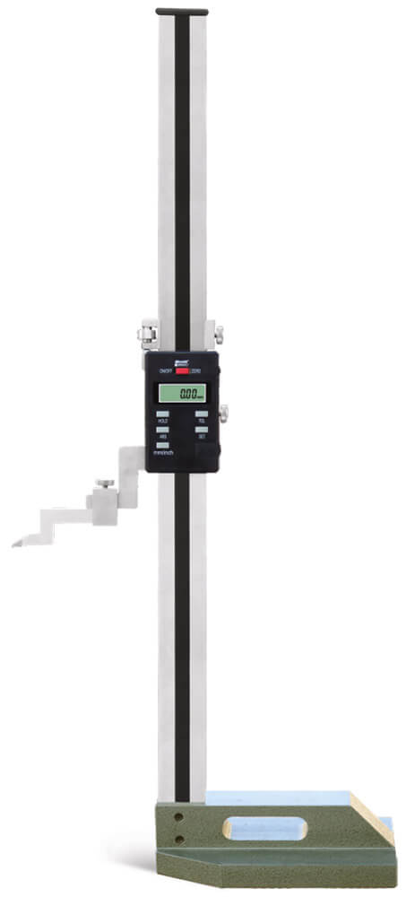 | Height Measurements Single Beam Digimatic Height Gauge Single Beam Digimatic Height Gauge The Single Beam Digimatic Height Gauge is a precision digital measuring and marking instrument designed for... View product → |
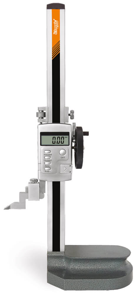 | Height Measurements Single Beam Digimatic Height Gauges with hand wheel Single Beam Digimatic Height Gauges with Hand Wheel The Single Beam Digimatic Height Gauge with Hand Wheel is a precision digital measuring... View product → |
Frequently asked questions
Why does a point micrometer give unstable readings on a single-beam height gauge?
The tip may shift laterally between measurements and contact an edge, burr, chamfer, or radius instead of the same geometric point.
How can you control point micrometer height measurement?
Clean all contact surfaces, secure the workpiece, align the tip consistently, and repeat the measurement from the same direction with controlled contact force.
How do you separate a height gauge fault from a point micrometer fault?
Test the gauge with a stable flat contact or reference standard, then compare repeatability with the point micrometer. Stable reference readings point to the contact tool or setup.
Which contact should you use for grooves, edges, and broad surfaces?
Use a narrow or knife-edge contact for grooves and defined edges, a ball contact for small curved features, and a broad flat or disc contact for stable surfaces.
What are the limits of a single-beam height gauge?
A single-beam gauge has limited rigidity, reach, and resistance to side loading. Specify the measuring range, resolution, repeatability, contact compatibility, and workload before buying.
Related products
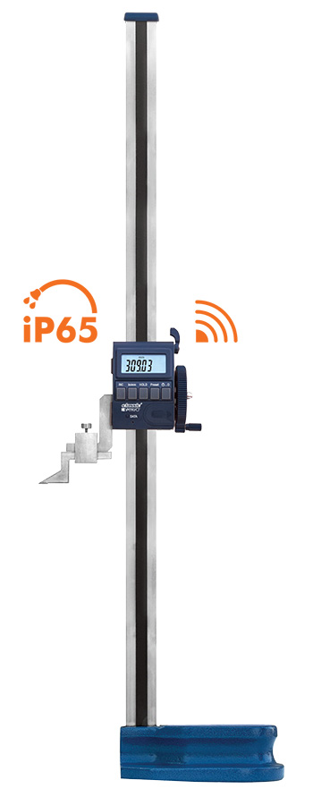 | Height Measurements Digimatic Single Beam Height Gauge with Bluetooth Digimatic Single Beam Height Gauge with Bluetooth The Digimatic Single Beam Height Gauge with Bluetooth is a precision digital measuring instrument... View product → |
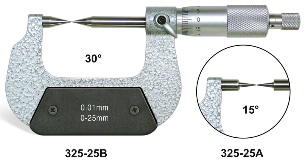 | Micrometers Point Outside Micrometers The Point Outside Micrometer is a specialized precision measuring instrument designed for measuring web thickness of... View product → |