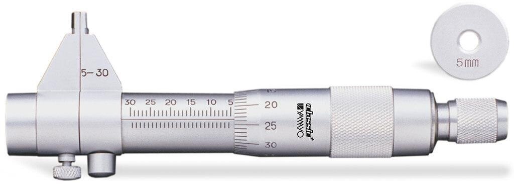
A correct internal measurement depends on more than turning the screw until the jaws touch the bore. You will learn how to select the contact geometry, set and align the jaws, find the true diameter, verify the instrument, and record a defensible final reading.
Key takeaways
- Choose jaw geometry that clears chamfers, radii, keyways, and burrs.
- Seat both jaws squarely; do not measure across a chord.
- Check multiple depths and angles before accepting the bore size.
- Lock, read, and record the dimension with its measurement location.
Choose the Jaw Geometry, Range, and Reference Before Turning the Screw
A two-point jaw-type inside micrometer must match the feature before you turn its screw. For a bore, choose opposed contacts that reach the intended diameter without catching a chamfer, radius, keyway, burr, or interrupted wall.
Select a measuring depth beyond the entrance and a range that places the working size within the instrument’s central operating span.
- Clean the contact faces, bore, and reference standard; remove chips, oil films, abrasive, and raised metal.
- Check the jaw shape and contact length against the bore, slot, recess, or blind-hole geometry.
- Confirm the graduation or resolution, stated accuracy specification, material, and calibration-certificate requirement.
- Use a setting ring, master ring, calibrated internal standard, or traceable length standard close to the working size; closing the jaws is not a valid zero check when they cannot meet or the range is large.
A search for a jaw type inside micrometer in Ludhiana is incomplete without these specifications. “Screw adjustment” also describes two different actions:
| Action | Purpose | Reference and result |
|---|---|---|
| Measurement adjustment | Opens or retracts the opposed jaws to fit the feature | The bore itself supplies the reference; turning the screw establishes a reading |
| Calibration adjustment | Corrects indication error in the sleeve, thimble, or reference setting | A certified standard supplies the reference; adjustment follows the manufacturer’s procedure |
Do not calibrate by forcing the jaws against a bore or by turning until the display agrees. That changes the measurement position, not the instrument’s accuracy.
Set the Screw and Seat the Jaws Without Measuring a Chord
Open the jaws until they clear the bore, then retract them slightly before insertion. Inside micrometer screw operation depends on the instrument’s thread direction, so confirm the marked expand/retract direction by watching the jaws move; never assume clockwise always opens them.
One complete screw revolution moves the jaws by the screw pitch, while the thimble divisions show the fractional movement. Turn slowly as the contacts approach the surface.
1. Insert the jaws squarely into the bore, keeping the micrometer axis as close as possible to the bore axis. Do not force a jaw past a chamfer, burr, radius, keyway, or interrupted surface.
2. Expand the jaws until both contacts touch opposite walls. Use light, consistent contact force; excessive force can flex the instrument or distort a thin-walled part.
3. Gently rock or sweep the instrument through a small angle while maintaining contact. A tilted position spans a chord and produces a reading smaller than the true two-point diameter.
4. Stop at the maximum stable reading. This position places the opposed jaws across the diameter rather than along a chord, giving the correct jaw micrometer internal measurement.
A lock preserves the screw setting for removal or comparison; it does not correct poor alignment or contact-force error. If the reading changes sharply during the sweep, ease the jaws back, reseat them, and repeat rather than averaging the values. Take the final reading only after the maximum position repeats.
Map the Bore at Multiple Depths and Angular Positions
Take readings at several depths and at two angular positions at each depth; one diameter cannot reveal bore form. A jaw micrometer internal measurement becomes a size map when you keep the axis close to the bore axis, gently rock through the opening, and record the maximum stable reading rather than a tilted chord.
- Mark the mouth, middle, and bottom measurement planes. Add more planes near a suspected defect or transition.
- At each plane, measure with the instrument in one orientation, then rotate the part or instrument approximately 90 degrees and repeat. Keep the jaw contacts on the specified datum, not on a chamfer, radius, burr, or keyway.
- Repeat any result that changes when you sweep the instrument. A low value from a tilted position is a chord, not the bore diameter.
- Compare both angular readings within each plane and compare each plane with the others.
| Pattern | Interpretation |
|---|---|
| Nearly equal readings at every plane and angle | Straight and round within the observed locations |
| Diameter changes progressively from mouth to bottom | Taper |
| Largest diameter at the mouth, then smaller inside | Bell mouth |
| Smaller diameter at the mouth, then larger inside | Barrel shape |
| Two readings about 90 degrees apart differ at one or more planes | Ovality or local out-of-roundness |
| Irregular changes between adjacent planes | Bore damage, waviness, interrupted geometry, or a measurement-location error |
A two-point jaw instrument reports the contact diameter at selected locations; it does not replace a three-point bore micrometer for roundness characterization. Record depth, angle, reading, contact style, and repeatability with every map.
Read, Lock, and Record the Final Dimension Correctly
Take the final reading only after the jaws reach the maximum stable value while you gently sweep the instrument through the bore. Lock the screw without shifting the contact position; the lock preserves the setting but does not correct a chord measurement or contact-force error.
Correct inside micrometer screw operation ends with the jaws seated on clean, uninterrupted surfaces and the axis aligned with the bore. Record each depth and the reading after rotating the part or instrument approximately 90°; one value cannot reveal taper, bell-mouth, or ovality.
| Instrument type | How to read the final dimension | Recording rule |
|---|---|---|
| Sleeve-and-thimble | Add the sleeve’s whole-unit and half-unit marks to the thimble graduation aligned with the reference line. | Record only the thimble’s stated increment. |
| Vernier | Read the sleeve and thimble, then identify the vernier line that aligns exactly with a thimble graduation. | Do not add digits beyond the vernier resolution. |
| Dial | Read the fixed scale or reference value, then add the dial-pointer indication in the instrument’s marked direction. | Confirm whether clockwise movement increases or decreases the dimension. |
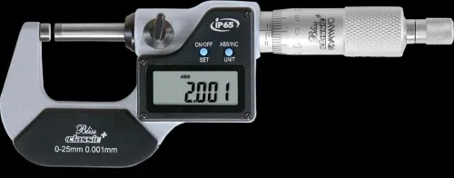
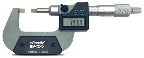
| Digital | Wait for a stable display after seating and locking the position. | Record the displayed unit, resolution, and any sign or mode indicator. |
Report the dimension with the instrument’s actual resolution and applicable accuracy or calibration uncertainty. A display showing 0.001 mm does not prove accuracy to 0.001 mm; include the depth, angular position, and any observed variation.
Verify the Setting and Specify the Right Instrument for Purchase
Check accuracy against a setting ring, master ring, or traceable internal standard close to the working size; closing the jaws is not a valid zero check when they cannot meet. Stabilise the instrument, standard, and part near 20 °C before a high-accuracy comparison.
Give a supplier these specifications:
- Working range, including the minimum and maximum bore sizes
- Graduation or digital resolution
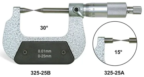
- Jaw geometry and contact shape for a bore, slot, recess, or blind hole
- Measuring depth and required reach
- Jaw and frame material, especially when measuring hot, soft, or dissimilar parts
- Required accuracy tolerance and the calibration method used to verify it
- Calibration certificate requirement, including traceability and the reference size
- Any locking, ratchet, or coolant-resistant feature needed in production
Repeat the same reference measurement several times while approaching from the same direction. Then open the jaws, re-enter the ring, and repeat; the spread between readings is repeatability. Scatter points to inconsistent force, dirt on the jaws, screw or frame looseness, poor alignment, or damaged contacts even when the average is correct.
A search for jaw type inside micrometer in Ludhiana should include those specifications, not just the product name. The longer phrase jaw type inside for micrometers screw adjustment in Ludhiana describes a search, not a metrology classification. Yamayo Instruments can help compare the requested range, jaw form, depth, certificate, and stated accuracy before purchase.
Related product
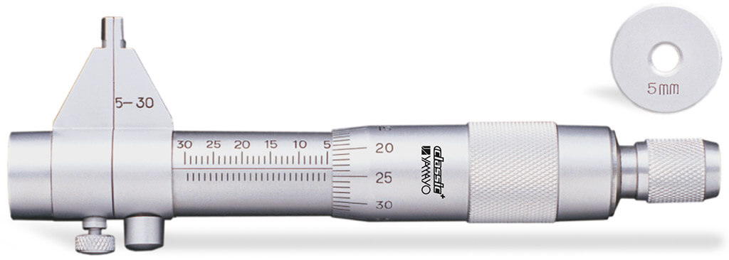 | Micrometers Jaw Type Inside Micrometers The Jaw Type Inside Micrometer is a precision measuring instrument designed for accurate internal diameter (ID)... View product → |
Frequently asked questions
How do you choose the correct jaw geometry and range?
Match the opposed jaws to the bore’s diameter, depth, wall shape, and access. Confirm they contact the intended cylindrical surface without catching a chamfer, radius, keyway, burr, or interrupted wall.
How do you operate the inside micrometer screw correctly?
Set the screw near the expected size, insert the jaws without forcing them, and adjust until both contacts seat on opposite walls. Rock the instrument through the bore axis to avoid measuring a chord.
How should you map a bore with a jaw-type inside micrometer?
Measure at multiple depths and at several angular positions, including positions across suspected high and low points. Record each reading and identify the location where it was taken.
How do you verify and record the final inside-micrometer reading?
Lock the setting, confirm the scale and thimble reading, recheck the contact position, and record the dimension with units, depth, angular position, instrument identification, and reference standard.