A reliable tube measurement starts by identifying whether you need outside diameter, local wall thickness, inside diameter, or ovality. You will be able to choose the correct contact geometry, prepare the tube, apply repeatable force, and record a reading that reflects the part rather than a burr, dent, or alignment error.
Key takeaways
- Choose the micrometer from the controlled tube dimension and drawing tolerance.
- Clean the tube and contacts before checking zero and taking readings.
- Align the points across the tube and use the ratchet for repeatable force.
- Measure multiple positions to detect ovality, taper, or inconsistent diameter.
Identify the Tube Dimension and the Micrometer Type
Choose the instrument by the dimension controlled on the drawing, not simply by calling the part a tube.
| Instrument | Contact geometry | Measures | Main caution |
|---|---|---|---|
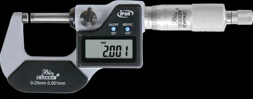
| Outside micrometer for tubes | Spherical, cylindrical, or V-anvil contacts | Tube outside diameter (OD) | A single reading is local; it does not prove maximum OD |
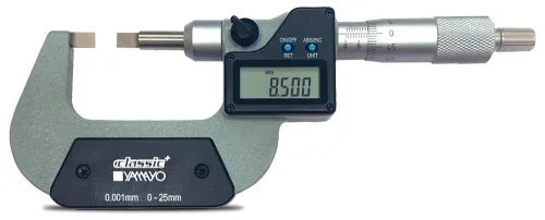
| Tube-wall micrometer | Contacts shaped to seat on the tube’s inner and outer surfaces | Local wall thickness directly | Match contact radius and force to the wall and surface |
| Inside micrometer or bore gauge | Internal measuring contacts | Inside diameter (ID) | Access and bore alignment affect the result |
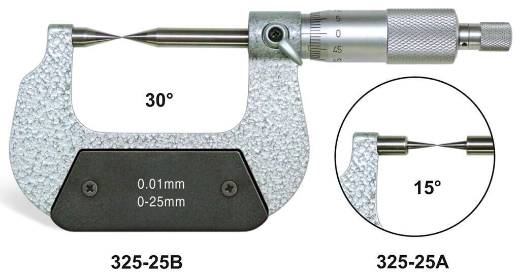
| Point micrometer for tubes | Pointed or conical contacts | Narrow grooves, recesses, shoulders, or restricted features | Small tips respond strongly to burrs, roughness, coatings, and dents |
A point micrometer uses pointed or conical contacts to reach a restricted feature. It is not automatically the correct choice for tube-wall measurement. A tube outside micrometer uses contact geometry intended to seat on curved tubing surfaces, while direct wall measurement avoids treating OD and ID as substitutes.
Calculating wall thickness as t = (OD − ID)/2 combines errors from two measurements and can hide local eccentricity. Use it only when the geometry and uncertainty are acceptable.
To check ovality, rotate the tube through several angular positions and measure at more than one axial location. Compare the readings as a range, rather than reporting one local diameter.
Prepare the Tube, Contacts, and Zero Check
Before the spindle touches the tube, let the micrometer, tube, and reference standard reach a stable temperature. Temperature differences can shift the reading before measurement begins.
- Wipe oil, chips, paint flakes, loose scale, and other contamination from the tube’s contact areas.
- Inspect those areas for burrs, weld beads, dents, and raised coating. Remove or record any feature that changes the intended measurement.
- Clean the anvil and spindle faces with a lint-free cloth; do not trap debris between the contacts.
- Close the micrometer using its ratchet or friction thimble, not by gripping and forcing the thimble.
- Compare the closed reading with the marked zero, or with a certified setting standard appropriate to the instrument’s range.
| Check | What it tells you | What it does not tell you |
|---|---|---|
| Zero check | Whether the closed instrument agrees at one position | Accuracy across the measuring range |
| Certified setting standard | Agreement at a specified dimension | Linearity or repeatability at other dimensions |
| Multi-point verification | Performance at several defined dimensions | That a damaged or contaminated tube is acceptable |
Use multi-point calibration or verification when the instrument will support acceptance decisions, the tolerance is tight, the range is broad, or a zero check fails. A correct zero cannot reveal a scale error, worn contacts, or poor performance away from the closed position.
Align the Contacts and Apply Repeatable Measuring Force
1. Place the tube squarely between the anvil and spindle. For an outside-diameter reading, align the spindle axis across the intended diameter; for wall thickness, align it radially through the two opposite walls. An angled spindle can slide onto another surface and give a falsely high or low result.
2. Centre a spherical or ball-type contact on the curved tube surface. Its rounded face seats against the local curvature instead of touching on a sharp edge. Pointed or conical contacts reach grooves and restricted features, but their small tips magnify the effects of dents, burrs, roughness, and coating thickness.
3. Close the spindle with the ratchet or friction thimble. Turn the ratchet until it slips or the friction thimble reaches its controlled setting; do not grip the thimble or force the spindle by hand. Operator strength then changes the result.
4. Use extra care with thin-wall tubing. Excessive force can dent or flatten the wall, damage a coating, or elastically deform the tube, producing an unstable reading that changes as the contact settles. A broad, spherical, or V-anvil arrangement can reduce local distortion when the instrument suits the tube.
Specify this alignment and force requirement when searching for a tube outside micrometer in Ludhiana or a point micrometer for tube measurement in Ludhiana.
Take the Reading and Test the Tube at Multiple Positions
Obtain the final value without moving the instrument from the intended contact location. Apply the controlled force with the ratchet or friction thimble, wait for the display or graduated scale to settle, then record the value, units, instrument identification, and measurement location.
Repeat the reading without changing the setup. Then rotate the tube through several clock positions and measure at more than one axial location; record every result rather than keeping only the first tube diameter micrometer reading.
A range across positions can reveal:
- Different readings around one cross-section: ovality, a dent, or eccentricity.
- A steady change along the length: taper or inconsistent wall thickness.
- An isolated high or low result: a weld seam, burr, loose scale, or surface damage.
Report maximum and minimum values when the specification controls limits, ovality, clearance, or worst-case fit. Otherwise, report the individual readings and their range so another person can see the variation.
Do not assume wall thickness from t = (OD − ID)/2 is equivalent to a local wall reading. It combines errors from two measurements and can conceal eccentricity when thick and thin areas occur at different locations. Use direct wall measurement when the requirement controls local thickness.
Select a Tube Diameter Micrometer for the Tolerance
Choose a tube diameter micrometer by the controlled tolerance, contact geometry, and measurement conditions—not by display resolution alone.
| Requirement | Specify | Why it matters |
|---|---|---|
| Range | Tube diameter and wall-thickness range; frame capacity | A limited throat or insufficient opening prevents access or forces an unsuitable setup. |
| Geometry | Anvil and spindle shape, contact radius, and access clearance | Ball, cylindrical, broad, or pointed contacts seat differently on curved, grooved, or restricted features. |
| Indication | Graduated or digital display, resolution, and units | A 0.001 mm increment shows readability, not accuracy. |
| Force and material | Measuring-force control and suitability for thin-wall tubing | Excess force can dent, flatten, coat-damage, or elastically deform the tube. |
For a purchase or acceptance decision, request the maximum permissible error, repeatability, calibration method, calibration points, and traceability to a stated standard. A digital instrument displaying 0.001 mm can have error and repeatability limits larger than 0.001 mm.
Define the reference condition as 20 °C for the micrometer, tube, and setting standard. Steel expands about 1.15 µm per 100 mm for each 1 °C change, so temperature differences can consume a tight tolerance before measurement begins. Require the supplier to state the uncertainty or correction policy, not merely the resolution.
State the Requirement Clearly When Buying or Verifying the Instrument
An outside tube micrometer supplier cannot quote intelligently from “tube measurement” alone. State the controlled feature and inspection conditions before requesting a quotation or calibration.
1. Controlled dimension: tube OD, local wall thickness, ID, groove depth, or another feature. Say whether the measurement is local or across the full circumference.
2. Tube details: material, nominal diameter, wall-thickness range, specified tolerance, and whether the surface has scale, paint, plating, welds, burrs, or dents.
3. Access: describe restricted clearance, groove width, axial reach, and any area the frame or contacts cannot enter.
4. Contact geometry: request pointed, conical, spherical, cylindrical, V-anvil, or another form that matches the drawing datum and surface. Specify controlled measuring force.
5. Performance: state required resolution, maximum permissible error or accuracy, repeatability, and reporting units. A 0.001 mm display does not prove 0.001 mm accuracy.
6. Calibration: list the required points across the range, certificate or traceability requirement, and reference standard.
7. Temperature: define the 20 °C reference condition, stabilisation time, allowable variation, and whether thermal correction is permitted.
Searches for point micrometer for tube measurement in Ludhiana can describe different tools. Yamayo Instruments can discuss these requirements, but you must define the inspection method before treating any quotation as suitable.
Related product
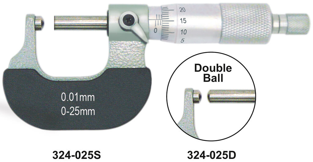 | Micrometers Tube Outside Micrometers The Tube Outside Micrometer is a precision measuring instrument specially designed for accurate measurement of tube wall... View product → |
Frequently asked questions
How do you identify the correct micrometer for a tube?
Read the drawing to determine whether you must measure outside diameter, inside diameter, wall thickness, or another feature. Select the corresponding micrometer type and range, then confirm its resolution and accuracy cover the stated tolerance.
How do you prepare a point micrometer before measuring a tube?
Clean the tube surface and pointed contacts, remove burrs, close the spindle gently, and check the zero reading. Use a certified reference or setting standard when the instrument range requires one.
How should you align a point micrometer on a tube?
Place the contacts on the intended measurement line, keep the spindle square to the tube surface, and close the instrument with the ratchet or friction thimble. Do not force the frame or tilt the micrometer.
Why measure a tube at multiple positions?
Measurements around the circumference reveal ovality, while readings along the length reveal taper or local deformation. Compare the results with the drawing tolerance rather than accepting one reading.
What should you state when buying or verifying a tube diameter micrometer?
State the dimension, measurement range, required resolution, accuracy or tolerance, contact shape, calibration requirement, and whether you need an outside tube micrometer for a particular tube material or geometry.