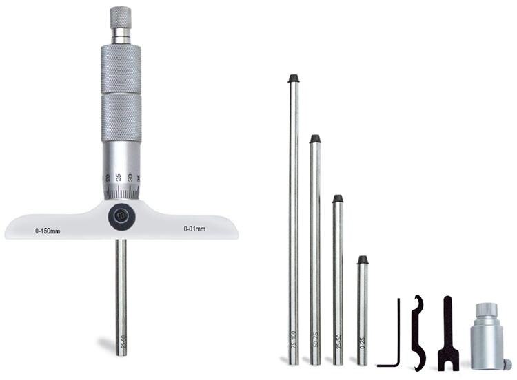
A depth reading is only as trustworthy as the datum, rod seating, contact force, temperature, and scale interpretation behind it. By the end, you will be able to operate a manual instrument consistently, identify false readings, verify performance, and select a configuration that suits the feature and its tolerance.
Key takeaways
- Match the rod range to the feature and seat the base fully on the datum.
- Turn the thimble steadily until contact is established without forcing the spindle.
- Repeat readings and record the rod, resolution, temperature, and verification result.
- Zero the instrument and verify it against a known reference before inspection.
How the screw mechanism turns rotation into depth
Rotating the thimble drives a precision screw, converting angular motion into axial spindle travel. The screw pitch sets the distance advanced in one complete revolution; for example, a 0.5 mm pitch moves the spindle 0.5 mm per revolution.
The graduated sleeve records the larger movement along the spindle axis, while thimble graduations divide one revolution into smaller readable increments. A manual depth micrometer reading combines both scales: identify the last visible sleeve graduation, add the aligned thimble graduation, and apply the stated resolution.
Read the marks squarely, with your eye perpendicular to the sleeve and thimble scales. Viewing from an angle creates parallax and can shift the apparent alignment.
A ratchet or friction thimble controls contact force by limiting how much torque reaches the screw after the spindle touches the surface. It improves consistency between readings; it does not prove the instrument’s accuracy.
| Term | What it means | Why it matters |
|---|---|---|
| Resolution | Smallest displayed or readable increment | A 0.01 mm reading does not guarantee 0.01 mm accuracy |
| Permissible error | Maximum deviation allowed by the specification | Compare it with the part tolerance |
| Repeatability | Agreement between repeated readings under the same conditions | Reveals technique and contact variation |
| Calibration uncertainty | Uncertainty attached to the calibration result | Limits confidence in the stated correction or error |
Treat resolution as readability, not measurement capability. Acceptance decisions require the stated permissible error, repeatability, and calibration uncertainty as well.
How to establish the datum and take a depth reading
Set the datum before touching the thimble: the underside of the base is the reference plane, so place it fully on a defined, flat surface. A false datum adds or removes material from the measurement and reports the wrong depth.
Use this depth micrometer measurement method:
- Clean the base, the workpiece opening, and the bottom feature.
- Inspect for chips, oil, paint, burrs, raised edges, shoulders, radii, and uneven cast surfaces.
- Select a rod that reaches the bottom without exceeding its range. Fit it fully into the socket, tighten it securely, and confirm its length or range.
- Keep the base supported while advancing the spindle with the thimble or ratchet.
- In a hole or recess, rock the supported tool lightly to locate the lowest stable reading. Do not tilt the base or rod.
- Read the scale squarely, then record the reading, rod identification, and feature location.
| Condition | Effect on the reading | Control |
|---|---|---|
| Clean flat datum | Establishes the intended reference plane | Seat the entire base without rocking |
| Chip, paint, or raised edge | Adds apparent depth or prevents full seating | Remove it and inspect again |
| Burr or shoulder at the opening | Stops the rod short and gives a shallow reading | Deburr or position away from the obstruction |
| Radius or uneven cast surface | Produces contact at an inconsistent point | Use a defined flat datum or a suitable narrower base |
| Angled rod | Gives an unstable or falsely shallow depth | Keep the rod normal to the bottom and repeat the light rocking check |
A rod catching on a burr can shift between readings; a tilted instrument can hide that error behind a seemingly stable number.
How rods, contact force, and repeated readings affect reliability
An unseated rod can shift every result by the same amount, so repeated readings will not expose the error. A depth micrometer for inspection is reliable only when the rod, contact force, and datum are controlled together.
- Select a rod whose marked range contains the feature depth. Match the rod length to the scale or reference setting; a 0–25 mm range cannot cover a 25–50 mm feature without the correct extension.
- Wipe the rod end and socket clean. Remove chips, oil, and burrs, push the rod fully into the socket, tighten it securely, and confirm its engraved identity before measuring.
- After every rod change, close the tool on a clean reference or use a known setting standard. A wrong rod length or incomplete seating creates systematic error that repetition cannot reveal.
- Rest the base fully on the datum and use the same ratchet action for every reading. Advance until contact, rock the tool lightly where appropriate to find the lowest stable reading, and measure at several locations instead of accepting first contact.
- Record the rod length or range, feature location, and observed variation. Stop and investigate an unstable result: a rod catching on a burr can give a falsely shallow reading, while ratchet force can indent soft material or deflect thin sheet.
Base width changes the trade-off. A narrow base enters restricted openings but is less stable on a small or irregular datum; a wider base provides better support but can bridge an opening or block access to a recess.
How to zero, verify, and control measurement errors
Close the spindle against a clean, suitable reference surface before use and check whether the scale reads zero. A zero check catches a gross offset, but it cannot reveal screw nonlinearity, rod-length error, or error near the top of the range.
| Zero check | Confirms the closed-position offset | Pre-use setup and after changing a rod |
|---|---|---|
| Multi-point verification | Tests performance across the working range | Acceptance decisions and periodic checks |
Verify at more than one point with traceable gauge blocks, calibrated setting standards, or a suitable certified reference artefact. Compare the observed readings with the instrument’s stated permissible error and your part tolerance.
Control the main error sources directly:
- Let the instrument and part stabilise at the required inspection temperature; do not assume 20 °C. Steel expands about 11–12 µm/m·°C, so a 100 mm span exposed to a 5 °C difference can shift roughly 5.5–6 µm before workpiece expansion is considered.
- Hold the frame by a non-measuring area, or do not grip it during precision work; hand heat changes the reading.
- Remove dirt and oil from the base, spindle, rod, and contact faces.
- Deburr the feature edge, or reject the part when damage prevents a sound contact.
- Keep the base fully flat on the datum; rocking or tilting creates a false depth.
- Apply the same ratchet action and force for every reading.
- Inspect contact surfaces for scoring, rounding, looseness, or wear; remove damaged instruments from acceptance work.
How to choose and document a depth micrometer for inspection
A 0–25 mm micrometer cannot inspect a 25–50 mm feature without the correct extension rod or another range model. Choose from the feature and decision risk, not nominal range alone.
| Decision point | What to compare | Risk controlled |
|---|---|---|
| Required range | Working depth, including rod range | Measuring beyond scale |
| Base geometry | Width, flatness, and stability | Rocking or datum error |
| Access opening | Base and rod clearance | Tool cannot seat fully |
| Rod system | Interchangeability and secure seating | Wrong or loose rod |
| Resolution | Smallest displayed increment | Misreading fine changes |
| Maximum permissible error | Stated MPE against part tolerance | False acceptance |
| Repeatability | Spread from repeated readings | Unstable results |
| Calibration uncertainty | Uncertainty against tolerance | Overconfident decisions |
| Force control | Ratchet or friction thimble | Variable contact force |
| Scale legibility | Clear graduations and markings | Reading and parallax errors |
| Calibration records | Traceability, date, interval, results | Unverifiable measurements |
For a screw type depth micrometer for measurement in Ludhiana, Yamayo Instruments can help match the base, rod system, range, and calibration records to the task. Request and record:
- Instrument serial or asset number, nominal range, resolution, selected rod, and calibration status.
- Environmental conditions where relevant, the measured feature, and reference-standard results.
A manual model suits areas where battery or display failure is unacceptable. It still exposes you to reading, parallax, force, and rod-identification errors, so the procedure must control each one.
Frequently asked questions
How does a depth micrometer screw mechanism convert rotation into depth?
The thimble turns a precision screw. The screw pitch determines spindle travel per revolution; a 0.5 mm pitch advances the spindle 0.5 mm in one complete turn.
How do you take a depth micrometer measurement?
Clean the feature and base, seat the base on the datum, select a rod covering the depth, and turn the thimble until the contact point is reached. Take repeated readings from the same setup.
What affects the reliability of a manual depth micrometer reading?
Base seating, rod alignment, contact force, spindle condition, temperature, and operator technique all affect the result. Use consistent force and repeat the measurement.
How should you verify and document a depth micrometer for inspection?
Check zero with the contact retracted or against the instrument’s specified reference, verify readings against a suitable known standard, and record the instrument identity, rod used, resolution, temperature, and result.