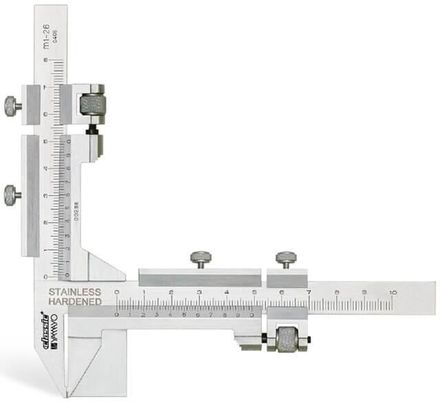
The right instrument depends on the dimension your drawing specifies and whether the tool can physically reach the intended contact points on the tooth. By comparing contact geometry, gear conditions, setup technique, and inspection requirements, you can choose between a gear-tooth vernier, a gear-tooth micrometer, an ordinary screw gauge, or an over-pin method without mistaking one reading for another.
Key takeaways
- Use a gear-tooth vernier for chordal tooth thickness and addendum height.
- Do not use a vernier to measure a gear’s overall outside diameter.
- Use a screw gauge only when its anvils match the gear’s contact geometry.
- Choose the supplier after confirming the drawing dimension and required accuracy.
Which tool reaches the gear dimension you need?
Choose by the surfaces the instrument can physically touch. A gear-tooth vernier caliper uses its horizontal jaws on opposing tooth flanks and its vertical slide to set depth, giving a direct check of chordal tooth thickness and chordal addendum height. It does not measure overall outside diameter.
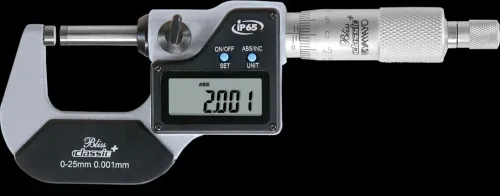
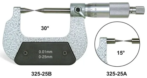
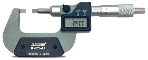
A conventional screw gauge has flat, parallel anvils. On an involute flank, they may touch at an uncontrolled point and produce a repeatable reading that is not the specified tooth thickness. A gear-tooth micrometer uses shaped disc, blade, or pointed anvils to control that contact.
| Instrument | Physical contact | Best first choice |
|---|---|---|
| Gear-tooth vernier caliper | Opposing flanks at a set depth; depth slide references the tooth tip | Quick chordal thickness and addendum checks across many external spur or helical gears |
| Ordinary screw gauge | Flat anvils on whatever part of the flank or outside surface they reach | Small accessible dimensions only, when the drawing defines that contact |
| Gear-tooth micrometer | Shaped anvils seat against selected tooth flanks | Finer tooth-thickness discrimination at a defined datum |
For internal teeth, narrow access, large face width, steep helix angle, small tooth spaces, or unusual pressure angles, jaw clearance and contact alignment can disqualify the vernier. Module or diametral pitch and tooth profile also determine whether its tooth-size range fits.
When comparing a gear tooth vernier caliper or screw gauge in Ludhiana, specify the gear’s geometry and inspection characteristic. Treat a screw gauge for gear measurement as suitable only when its anvil shape and contact location match the drawing or inspection method.
Match the instrument to the gear’s geometry
Use a gear-tooth vernier when the drawing calls for chordal tooth thickness and addendum height; use a gear-tooth screw gauge when shaped anvils can seat at the specified depth. An ordinary flat-anvil micrometer may slip on an involute flank and give a false reading.
| Gear geometry | Effect on tool selection |
|---|---|
| Module or diametral pitch | Determines tooth size, chordal setting, and the instrument’s supported range. |
| Pressure angle | Changes flank contact and the required tooth-depth setting. |
| Tooth count | Affects the chordal calculation and whether the jaws can enter the tooth space. |
| Helix angle | Requires helical-gear capability or suitable alignment; a spur-only tool can miscontact the flanks. |
| Face width | Determines whether the instrument reaches the usable measuring section without striking the shoulder. |
| Tooth profile | Involute, stub, crowned, or modified teeth need contact points suited to that profile. |
| Outside diameter | Helps establish access around external teeth but is not the chordal tooth-thickness result. |
| Internal or external teeth | External teeth are accessible to standard tooth calipers; internal teeth often need internal gear gauges or a different inspection method. |
The vernier measures a straight chord between flanks, not the circular arc at the pitch circle. For a standard spur gear, πm/2 is approximately the pitch-circle tooth thickness, but it cannot replace the specified vernier setting.
Gear tooth measurement tools in Ludhiana may include verniers, gear-tooth micrometers, span micrometers, and over-pin gauges, so match the instrument to the drawing’s stated method.
Set and use a gear-tooth vernier without changing the result
A correct reading starts with the drawing, not the caliper. Identify the specified chordal tooth thickness and chordal addendum height for that gear’s tooth count, module or diametral pitch, pressure angle, and standard; chordal thickness is not circular thickness at the pitch circle.
1. Clean the tooth and inspect both flanks, the tip, and the root for raised burrs from hobbing, broaching, or deburring. Remove loose burrs, but do not file the profile. A burr under a jaw produces a false thickness.
2. Set the vertical slide to the specified chordal addendum height, measured from the tooth tip toward the chordal thickness location. Lock the depth slide firmly; a shifted slide changes both the contact point and the result.
3. Place the caliper over the tooth with the depth blade seated on the intended tooth surface, not on a tip chamfer or an uneven edge. Keep the instrument square to the tooth face and parallel with the gear axis.
4. Bring the horizontal jaws onto the two opposing flanks at the set depth. Align them symmetrically; skewing the tool lets one jaw climb the involute and reads the tooth too thick or too thin.
5. Close with light, repeatable pressure until both jaws touch. Do not squeeze the flanks or force the slide past contact.
Take readings on several teeth and record the tooth positions. This repeat check exposes burrs, runout, or inconsistent alignment. Buyers comparing gear tooth vernier calipers in Ludhiana should confirm that the instrument’s depth range and jaw access suit the gear’s module, face width, and chamfers.
Use a screw gauge only when its contact geometry is defined
A zero reading does not make a flat-anvil micrometer suitable for a gear. On an involute flank, its parallel faces can touch at an uncontrolled location and give a repeatable reading that is not the specified tooth thickness.
- Clean the anvils and tooth flanks, then close the instrument gently with the ratchet. Confirm that the thimble and sleeve read zero; do not use it if the zero is outside the stated error limit.
- Align the spindle and anvil with the tooth’s measuring direction. Keep both contacts square to the face width and avoid burrs, chamfers, dirt, and the tooth tip.
- Seat the contacts on opposite flanks at the drawing’s specified depth. Turn the ratchet until it clicks or slips consistently; never tighten the thimble by hand.
- Take the reading without rocking the instrument. Repeat on several teeth and compare the spread before accepting the value.
| Instrument | Contact geometry | Suitable use |
|---|---|---|
| Ordinary outside micrometer | Flat, parallel anvils | Accessible flat surfaces or small outside dimensions, not automatic tooth-thickness checks |
| Gear-tooth micrometer | Disc, blade, or pointed shaped anvils | Defined flank contact at a specified tooth-thickness datum |
A gear-tooth micrometer offers finer resolution and controlled force, but those features do not correct poor alignment or the wrong anvil shape. Choose a screw gauge for gear measurement only when its contact geometry matches the drawing.
For a gear tooth vernier caliper or screw gauge in Ludhiana, specify the gear type, tooth-size range, module or diametral-pitch range, measuring range, resolution, and calibration laboratory scope.
Tie the reading to the drawing before choosing a supplier
A chordal reading is acceptable only when it matches the drawing’s stated chordal thickness and chordal height. Do not compare that value directly with circular tooth thickness at the pitch circle, or treat it as a measurement over pins.
| Option | Result produced | Use it when |
|---|---|---|
| Gear-tooth vernier | Chordal tooth thickness at a specified addendum height | You need a fast direct check across many parts |
| Gear-tooth micrometer or shaped-anvil screw gauge | Controlled flank-to-flank thickness | The drawing requires finer discrimination or a defined tooth-flank contact |
| Over pins or balls | Measurement across selected teeth | The drawing specifies pin or ball diameter and the production method |
| Gear analyser | Pitch, profile, lead, runout and helix errors | You need complete gear accuracy, not tooth thickness alone |
Before accepting a quotation for gear tooth measurement tools in Ludhiana, state the gear’s module or diametral pitch, pressure angle, tooth count, profile shift, helix angle, face width, and internal or external form.
A supplier who offers gear tooth vernier calipers in Ludhiana should confirm the measuring range, depth-slide range, resolution, and whether the jaws reach the tooth flanks without touching a chamfer or burr.
Ask Yamayo Instruments to identify the specified method on the quotation rather than accepting “gear measuring instrument.” A result over pins depends on pin diameter, tooth count, pressure angle and helix angle; it cannot replace a chordal reading without the correct gear calculation.
Reject a pass based only on tooth thickness when the inspection also requires pitch variation, radial runout, profile error, lead error or helix error.
Related products
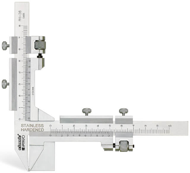 | Thickness Measurements Gear Tooth Vernier Caliper The Gear Tooth Vernier Caliper is a specialized precision measuring instrument designed for measuring gear tooth thickness... View product → |
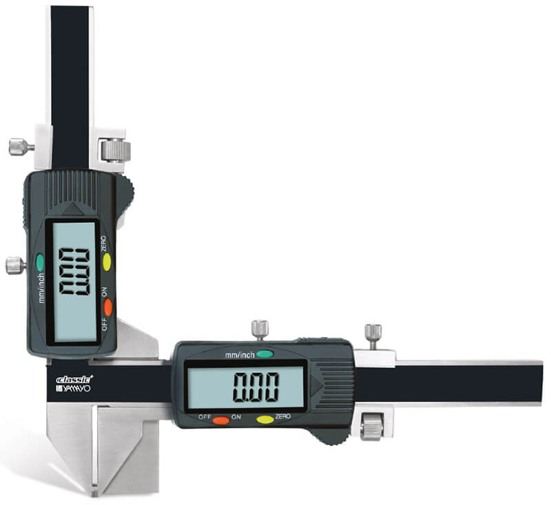 | Calipers Digimatic Gear Tooth Calipers The Digimatic Gear Tooth Caliper is a precision digital measuring instrument specifically designed for accurate... View product → |
Frequently asked questions
Which tool reaches the gear dimension you need?
Use a gear-tooth vernier for chordal tooth thickness and chordal addendum height. It does not measure overall outside diameter.
How do you match the instrument to a gear’s geometry?
Choose an instrument whose jaws, anvils, or contacts can physically reach the two surfaces defining the specified gear dimension.
How do you set and use a gear-tooth vernier without changing the result?
Seat the horizontal jaws on opposing tooth flanks and set the vertical slide to the specified measurement depth without tilting or forcing the instrument.
When is a screw gauge suitable for gear measurement?
Use a screw gauge when its contact geometry is defined for the surfaces being measured and the anvils can seat consistently.