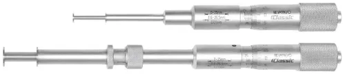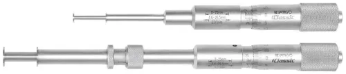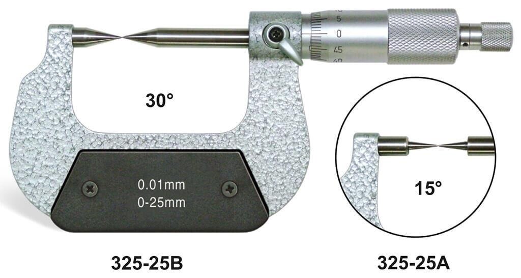
A point micrometer can give a stable, repeatable reading while touching the wrong flank, radius, or datum. You will learn how to set up the single-beam gauge, identify false height changes caused by alignment and contact, and decide when the measurement method or instrument needs attention.
Key takeaways
- Remove burrs and films before checking zero or blaming the gauge.
- Touch the point to the intended feature, not an adjacent shoulder or radius.
- Check cosine error, carriage movement, temperature, contamination, and battery status.
- Match verification frequency and data capture to the size of your tolerance.
Set the single-beam gauge and establish a trustworthy zero
1. Clean the surface plate, gauge base, carriage contact areas, and workpiece before diagnosing height gauge measurement problems. Remove chips, oil films, corrosion, and raised burrs; wiping alone will not remove a burr under the base or on the part. Inspect the plate and datum faces by touch and with suitable magnification.
2. Let the gauge, surface plate, reference, and workpiece reach the same room temperature before setting zero. Check that the beam is square to the plate and that the base sits flat. Measure a certified reference height at more than one horizontal position; a changing result indicates alignment, base, or carriage geometry.
3. Set zero from the datum you intend to report, not from a convenient surface. A surface-plate datum, part datum face, groove bottom, and edge produce different heights even when the point contact method is unchanged. Record the datum and contact location before taking the point micrometer height measurement.
4. Approach the known reference height from both directions and record readings with the carriage unlocked and locked. Tighten the lock without pushing the carriage or changing the contact; a single-beam carriage can twist or deflect under lateral force, especially high on the beam.
If locking changes the value, or the two approach directions disagree, inspect carriage play, attachment rigidity, and point alignment before measuring the part. Use controlled force and keep the point aligned with the feature rather than pressing the gauge sideways.
Use the point to locate the feature without measuring the wrong surface
A point micrometer height measurement is valid only when the point reaches the intended feature location, not merely the first surface it touches. Align the point with the groove, keyway, web, shoulder, scribed mark, or small-radius feature so its axis follows the feature direction and the tip approaches the intended centre, edge, or datum.
- Bring the point into contact with controlled, repeatable force; do not push the height gauge against the part.
- Keep the attachment square to the surface plate and avoid force that bends the point, rocks the workpiece, or shifts the gauge base.
- Repeat the approach from the same direction, then confirm that the reading returns when contact is released and remade.
A pointed tip can settle on a groove flank instead of its bottom, or on a chamfer, radius, burr, or rough patch. That contact can produce a stable, repeatable number that is still wrong. A narrow groove also invites side loading if the point is angled.
Decide what the reading represents. An absolute feature-height measurement reports the feature relative to the established datum; a locating use finds a contact point that you then read on the gauge or compare with another reference. Do not report the latter as a direct height without stating the comparison method.
Use a broad scriber or probe on soft, thin, rough, or damaged material. A sharp point can indent the surface or catch a raised defect, creating height gauge measurement problems that display resolution cannot reveal.
Separate a true part error from cosine error and carriage movement
A reading that changes with contact direction is not automatically a bad part. A tilted point micrometer or probe introduces cosine error: the contact path is not normal to the feature, so the point reaches a different apparent height as its approach angle changes.
A single-beam carriage can also twist or deflect, especially near the top of the beam, and tightening its lock can move the reading.
Use this troubleshooting sequence for height gauge measurement problems:
- Repeat the contact from both approach directions, using controlled force, and record the difference.
- Measure the same certified reference height at several horizontal positions on the surface plate.
- Repeat each position with the carriage unlocked, then locked; a lock-induced shift identifies carriage or attachment movement.
- Inspect the point micrometer, probe, adaptor, and mounting screws for looseness, tilt, bent parts, or a damaged contact point.
- Treat a consistent, position-independent difference from the certified reference as an instrument or setup error; a position- or direction-dependent difference points to geometry, cosine error, or deflection.
| Observation | More likely cause | Check |
|---|---|---|
| Changes with approach direction | Angled point or probe contact | Realign and repeat |
| Changes across horizontal positions | Beam squareness, base, or carriage deflection | Use the certified reference |
| Changes after locking | Carriage movement or attachment looseness | Compare locked and unlocked readings |
A 0.01 mm or 0.001 mm display indicates resolution, not accuracy, repeatability, scale linearity, or measurement uncertainty. These Digimatic single-beam height gauge issues require specification and calibration evidence, not extra decimal places.
Find contamination, thermal, and electronic causes of unstable readings
A chip under the base, an oil film on the datum, or a raised burr on the workpiece can add height directly. Do not diagnose digimatic single beam height gauge issues from the display alone; inspect the complete contact chain.
- Remove chips and oil films, then inspect for raised burrs, corrosion, and a damaged or rounded point tip.
- Check carriage locks, slides, attachment screws, beam joints, and rack-and-pinion parts for looseness or binding.
- Clean the scale-reading area with the manufacturer-approved method; dust, moisture, or salt deposits can interrupt readings.
- Fit a fresh battery, confirm the displayed origin, and rule out an unintended zero or preset operation.
- Flex the data cable gently and reseat connectors; intermittent contacts can create missing or implausible values.
In a Mumbai workshop, keep the base covered when idle, control dust, and wipe salt-bearing contamination from exposed steel and connectors. Apply only manufacturer-approved corrosion protection. Let the gauge, surface plate, and workpiece reach one temperature before measuring; moving equipment from air conditioning into warmer air can create condensation.
A 300 mm steel workpiece changes about 3.45 micrometres for every 1 °C change, using 11.5 micrometres per metre per °C. This is essential for point micrometer single beam height for gauge problems in Mumbai, but environmental care cannot correct geometric error, carriage deflection, or poor calibration.
Choose the right verification method and data workflow for your tolerance
Keep the point-micrometer method when the feature is accessible, the point seats consistently, and its repeatability is comfortably inside the tolerance.
Change the contact when the point lands on a radius, burr, chamfer, soft surface, or wrong groove flank; calibrate when results fail a reference check or the calibration interval has expired; move to a height master or CMM when the tolerance, geometry, or uncertainty exceeds the gauge’s demonstrated capability.
| Method | Use it when | Change or escalate when |
|---|---|---|
| Point micrometer | Narrow feature and controlled contact are repeatable | Contact location varies or damages the surface |
| Broad scriber or probe | Soft, rough, or damaged material | It cannot reach the feature without tilt |
| Height master | Direct comparison at a defined height | You need broader range or stronger verification |
| CMM | Complex geometry, multiple datums, or tight uncertainty | A simple feature does not justify the added setup |
Record the datum, contact location, approach direction, force-control method, repeated readings, calibration status, temperature, and whether the value is absolute or comparative. A comparative result is not an absolute height.
Do not buy on “Digimatic” alone; digimatic single beam height gauge issues include confusing resolution with accuracy. Specify maximum permissible error, repeatability, usable height range, resolution, calibration interval, data protocol, zero retention after battery replacement, and mechanical rigidity.
A Bluetooth height gauge in Mumbai improves transfer, not accuracy. Require pairing confirmation, unit control, part and operator identification, retransmission or local buffering, and an audit trail. Yamayo Instruments can help compare single-beam, point-contact, Bluetooth, and verification equipment against your tolerance and record format; wireless output is not calibration traceability.
Use a competent calibration laboratory meeting ISO/IEC 17025.
Related products
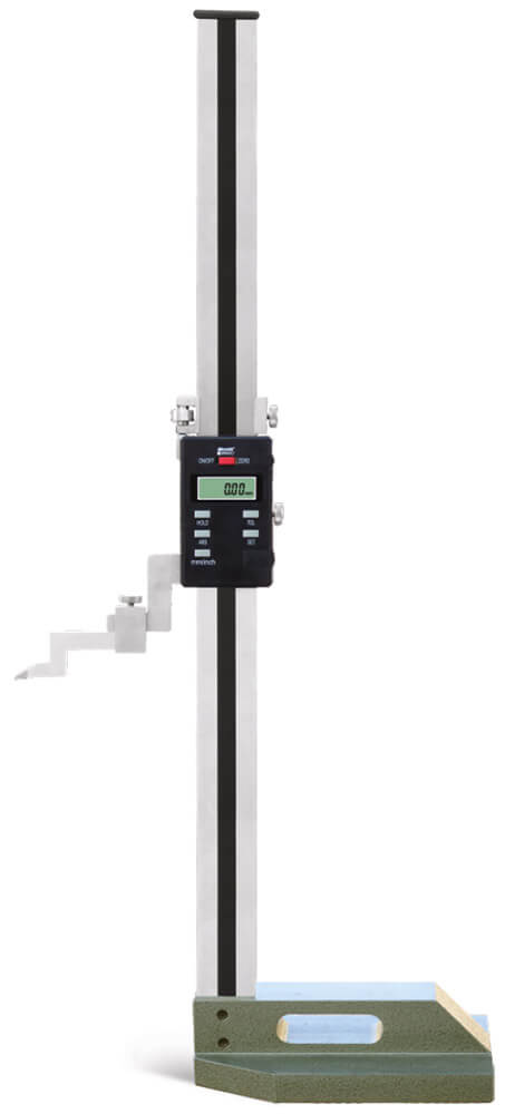 | Height Measurements Single Beam Digimatic Height Gauge Single Beam Digimatic Height Gauge The Single Beam Digimatic Height Gauge is a precision digital measuring and marking instrument designed for... View product → |
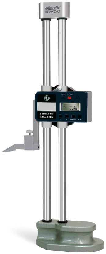 | Height Measurements Digimatic Double Beam Height Gauges Digimatic Double Beam Height Gauges The Digimatic Double Beam Height Gauge is a precision digital measuring instrument designed for accurate height... View product → |
Frequently asked questions
Why does a point micrometer on a single-beam height gauge give unstable readings?
Check for chips, oil films, burrs, corrosion, loose contact areas, temperature changes, battery problems, and electronic drift. Clean the surface plate, base, carriage, and workpiece before repeating the zero check.
How do you avoid measuring the wrong surface with a point micrometer?
Use the point to locate the specified feature deliberately. Confirm that it is touching the intended edge, groove, shoulder, or datum rather than a radius, chamfer, burr, or nearby surface.
How can you tell a true part error from cosine error?
Repeat the measurement with the point and carriage aligned to the measurement direction. Compare readings after reversing the approach or using a known reference; a geometry-dependent change indicates alignment or cosine error rather than a part change.
What should you check when a digimatic single-beam height gauge will not hold zero?
Inspect the plate, gauge base, carriage contact areas, and workpiece for contamination or burrs. Then check carriage locking, temperature, battery condition, encoder cleanliness, and zero stability against a suitable reference.
When should you verify height measurements with another method?
Use a calibrated height standard, gauge block stack, surface gauge, optical comparator, CMM, or another suitable method when the tolerance is close to the gauge uncertainty, readings remain unstable, or the result affects acceptance.
Related products
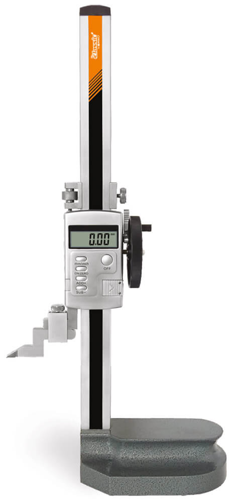 | Height Measurements Single Beam Digimatic Height Gauges with hand wheel Single Beam Digimatic Height Gauges with Hand Wheel The Single Beam Digimatic Height Gauge with Hand Wheel is a precision digital measuring... View product → |
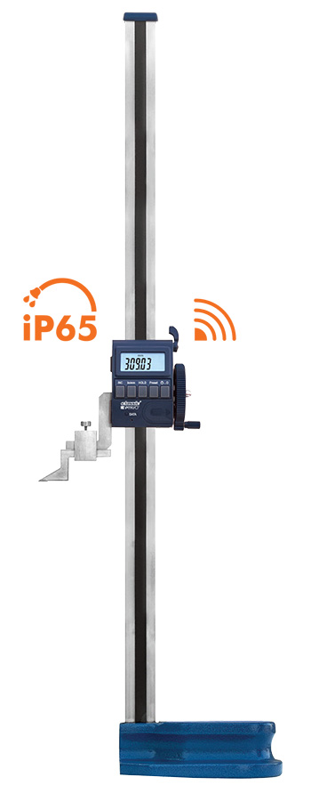 | Height Measurements Digimatic Single Beam Height Gauge with Bluetooth Digimatic Single Beam Height Gauge with Bluetooth The Digimatic Single Beam Height Gauge with Bluetooth is a precision digital measuring instrument... View product → |
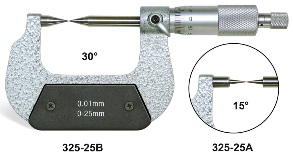 | Micrometers Point Outside Micrometers The Point Outside Micrometer is a specialized precision measuring instrument designed for measuring web thickness of... View product → |