A screw inspection becomes unreliable when the instrument is chosen by nominal diameter instead of the feature being measured. By separating shank, thread, groove, recess, and shoulder measurements, then specifying contact geometry and calibration evidence, you can request an instrument that reaches the feature and produces usable production data.
Key takeaways
- Use an outside micrometer for plain shank and head diameters only.
- Select blade, disc, ball, or pointed contacts to match the feature.
- Specify range, resolution, contact shape, calibration, and access before buying.
- Use thread gauges for acceptance; micrometers provide dimensional readings, not complete thread approval.
Choose the micrometer by the screw feature you need to measure
A standard outside micrometer belongs on a plain screw shank or head outside diameter. Its flat, parallel anvils contact the outer envelope; they bridge the thread flanks instead of locating the pitch line, so they cannot produce a reliable thread pitch-diameter result.
| Instrument | Measurement | Correct application |
|---|---|---|
| Standard outside micrometer | Outside diameter | Plain shank or head |
| Screw thread micrometer | Effective or pitch diameter | Pointed or conical spindle with a V-shaped anvil matched to the thread pitch |
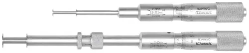
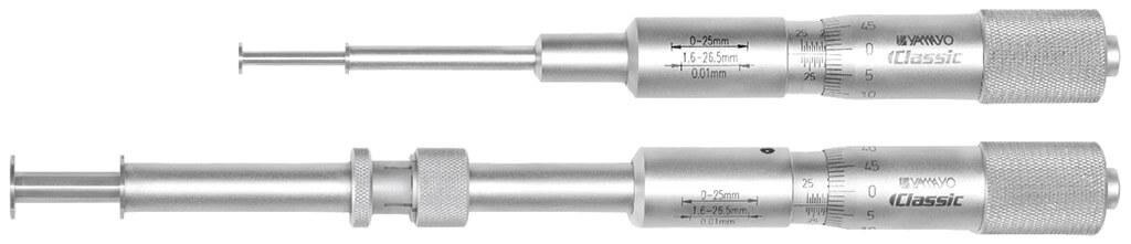
| Groove micrometer | Groove diameter, width, or shoulder distance | Under-head relief groove, narrow recess, or close shoulder |
| Blade outside micrometer | External groove or slot size | Accessible grooves and slots |
| Point outside micrometer | Restricted external feature | Webs, shoulders, and limited access |
| Depth micrometer | Depth from a reference face | Recess depth rather than diameter or width |
Do not confuse pitch diameter with major diameter, the thread’s outside crest diameter, or minor diameter, the root diameter. A functional GO/NO-GO thread gauge gives an assembly acceptance decision, not the variable pitch-diameter reading supplied by a screw thread micrometer. These are different inspection results.
A groove micrometer is not a substitute for a thread micrometer. Nominal screw diameter alone does not identify the instrument: confirm the characteristic, thread pitch, groove geometry, and access limits before ordering screw micrometers for manufacturers or comparing groove micrometers in Mumbai.
Match contact geometry to the groove, thread, or restricted feature
Disc or blade contacts enter a narrow groove when their thickness fits the opening and their faces reach the functional walls. Pointed contacts reach a web, restricted shoulder, or small external feature; V-shaped and conical contacts are required for thread pitch-diameter measurement because they engage the flanks at the specified pitch, not the crest.
| Contact geometry | Access and reading quality | Correct use |
|---|---|---|
| Disc or blade | Enters a narrow recess or slot | Groove diameter, width, or shoulder distance |
| Pointed | Reaches a web or restricted shoulder | Small external features |
| V-shaped and conical | Matches flank angle and pitch | Screw-thread pitch diameter |
Use this groove-measurement sequence:
- Remove chips and oil with a method that cannot scratch, smear, or reshape the feature.
- Inspect the groove for burrs, plating buildup, rolled edges, and damaged corners.
- Align the spindle with the groove so the contacts meet the intended surfaces squarely.
- Close the contacts with the ratchet or friction thimble, then seat them without rocking the instrument.
- Repeat the reading and compare the results.
Flank angle, interrupted or tapered geometry, rolled threads, rough surfaces, coatings, burrs, and damaged edges can all create false contact. A narrow contact may rest on a plating lump or burr instead of the functional surface.
Rotate or reposition the part only when the inspection method permits it. Reject any reading that lands on a burr, damaged flank, or coating lump; do not average it into acceptance. For groove micrometers in mumbai, specify the contact shape against the drawing rather than choosing by nominal screw diameter.
Build a buying specification for groove micrometers in Mumbai
Put the feature and access limits in the enquiry, not merely “groove micrometer.” This prevents a supplier from substituting a general outside micrometer or a thread gauge.
1. Attach the component drawing or a sketch showing groove width, depth, shoulder location, distance from the frame to the feature, and access limits. State metric or inch units, groove tolerance, screw standard and pitch, and whether the result is groove width, depth, diameter, or shoulder distance.
2. Specify measuring range, resolution, accuracy or maximum permissible error, repeatability, spindle travel, throat or frame clearance, contact-tip width or diameter, and the minimum groove width and depth. Two 0–25 mm instruments can have different spindle lengths, frame clearances, and contact shapes, so the same nominal range does not guarantee access.
A display resolving 0.001 mm does not prove 0.001 mm accuracy.
3. State the required ratchet or friction thimble, hardened or carbide contacts, data output such as USB or SPC, environmental protection, replacement-contact availability, and calibration documentation. Ask a groove micrometer supplier in Mumbai to confirm every item against the sketch before substitution.
4. For Mumbai procurement, require a calibration certificate naming the instrument serial number, measurement points, uncertainty or compliance statement, environmental conditions where relevant, and the laboratory’s accreditation scope. A supplier test certificate alone is not automatically ISO/IEC 17025 calibration.
Yamayo Instruments can be asked to review the sketch when quoting groove micrometers for screw options in Mumbai.
Related products
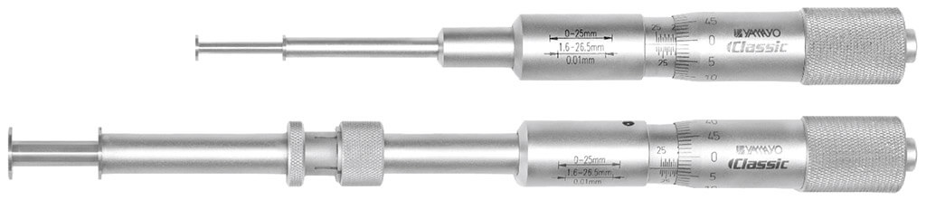 | Micrometers Groove Micrometers The Groove Micrometer is a specialized precision measuring instrument designed for accurate measurement of groove widths, groove... View product → |
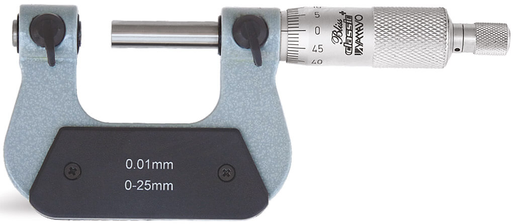 | Micrometers Screw Thread Micrometer The Screw Thread Micrometer is a precision measuring instrument specifically designed for accurate measurement of the pitch... View product → |
Separate dimensional readings from thread acceptance decisions
Do not release a threaded screw from one micrometer reading. First identify whether the drawing requires major diameter, minor diameter, pitch diameter, groove size, or assembly function; these results are not interchangeable.
1. For ISO metric threads, use ISO 1502 for terminology and gauging requirements. State the complete thread designation and pitch, such as M10 × 1.5, plus the required contact set; nominal diameter alone cannot identify the correct instrument.
2. Use a screw thread micrometer or three-wire method to obtain a variable pitch-diameter value from the flanks. A functional GO/NO-GO thread gauge tests assembly-related limits. Use screw micrometers for manufacturers during setup verification, sampling, and trend monitoring, not as the sole release decision for thread conformity.
3. Compare the result with the feature that matters. A screw can have an acceptable outside major diameter while its pitch diameter is wrong because of flank geometry, pitch error, or tool wear. The screw may still fail the mating gauge or assembly.
4. Write the control plan so each result has its own acceptance rule. Specify the characteristic, tolerance, measurement method, contact geometry, sampling frequency, and whether a functional gauge is mandatory.
5. Record enough information to reproduce the decision: part number, drawing revision, thread designation and pitch, characteristic measured, instrument serial number, operator, date, reading, units, and acceptance rule. Include the GO/NO-GO gauge identity and status when it determines release.
A supplier enquiry for groove micrometers for screw options should therefore separate groove measurement from thread acceptance and name the required characteristic rather than merely requesting a micrometer by nominal diameter.
Control temperature, force, and difficult features before accepting a reading
Do not accept a screw reading until the steel part and micrometer have stabilised in the inspection environment. Use 20 °C as the normal dimensional-metrology reference unless the governing procedure states otherwise. Keep a hot machined screw out of the acceptance queue until it reaches thermal equilibrium with the instrument and surrounding inspection area.
1. Check the contact faces for damage, swarf, oil, and plating deposits. Confirm the zero condition, repeatability, calibration status, and the correct contact geometry before measuring.
2. Use the ratchet or friction thimble consistently so contact force does not vary between readings. Controlled force cannot correct poor alignment, a damaged contact tip, contamination, or an unsuitable groove or thread geometry.
3. For coated, plated, rolled, tapered, interrupted, or burr-marked features, record the treatment condition. Inspect several positions when the feature permits, and distinguish coating thickness, plating buildup, or edge damage from the underlying dimension.
4. Align the micrometer with the feature and seat the contacts without rocking. For groove micrometers for screw options in Mumbai, include the part condition and inspection positions in the procedure; the same discipline applies when comparing groove micrometers in Mumbai.
If readings change with orientation, contact position, or applied force, stop acceptance. Investigate the feature, setup, or instrument instead of averaging the numbers. A clean-looking display does not make an unstable contact a valid measurement.
Frequently asked questions
Which micrometer should you use for measuring a screw feature?
Use a standard outside micrometer for plain shank or head diameters. Choose a groove, blade, disc, ball, or pointed-contact micrometer when the feature is recessed, threaded, narrow, or difficult to access.
How do you match micrometer contact geometry to a groove or thread?
Select contacts that reach the measurement surface without bridging it. Blade contacts suit narrow grooves, disc contacts reach shoulders and recesses, while ball or pointed contacts locate specific curved or angled surfaces.
What should you include in a buying specification for groove micrometers in Mumbai?
State the measuring range, resolution, accuracy, contact form, anvil and spindle material, frame clearance, ratchet or friction thimble, calibration requirements, and access limits on the screw.
Can a micrometer decide whether a screw thread passes inspection?
No. A micrometer gives a dimensional reading at the contacted feature. Thread acceptance requires the specified thread standard, pitch, class, and suitable gauges such as GO and NO-GO gauges.
How can you control errors when measuring grooves and restricted screw features?
Bring the micrometer and workpiece to a stable reference temperature, clean both contacts, use consistent ratchet force, align the tool with the feature, and repeat readings before accepting the result.
Related products
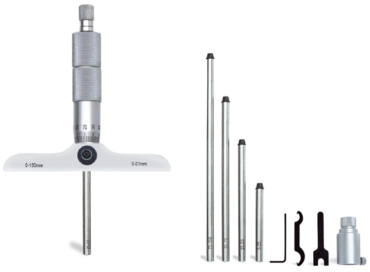 | Depth Measurements Depth Micrometers The Depth Micrometer is a precision mechanical measuring instrument designed for accurate measurement of depths, grooves, slots,... View product → |
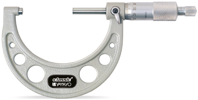 | Micrometers Outside Micrometers The Outside Micrometer is a precision measuring instrument designed for accurate external dimension measurement of components,... View product → |
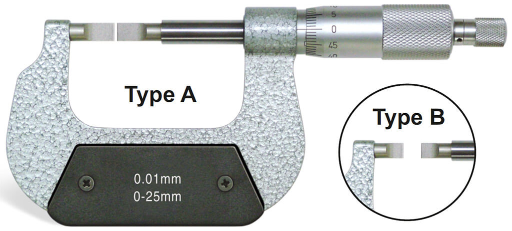 | Micrometers Blade Outside Micrometer The Blade Outside Micrometer is a specialized precision measuring instrument designed for measuring groove diameters, shaft... View product → |
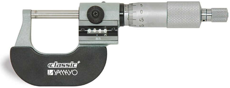 | Micrometers Digit Micrometers The Digit Micrometer is a precision mechanical measuring instrument designed for fast, accurate, and error-free external... View product → |