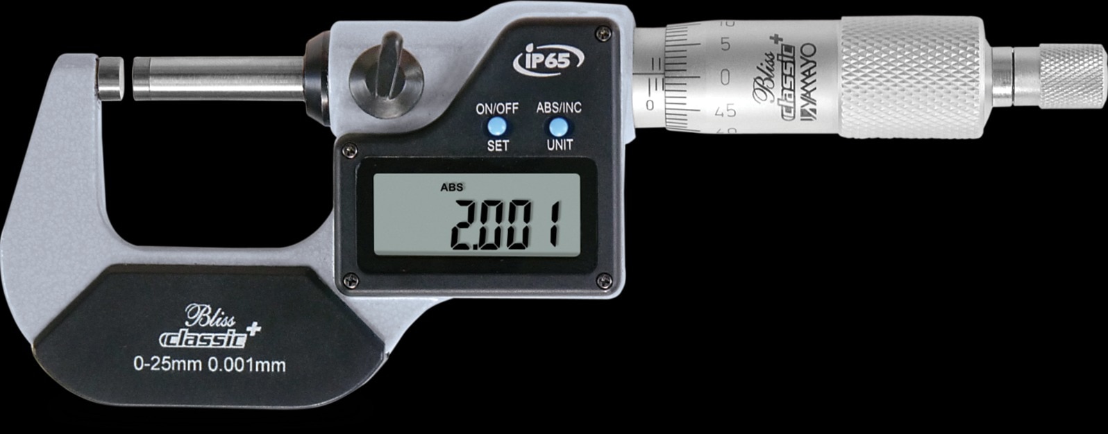
A zero that is off by 0.003 mm, a last digit that jumps, or a reading that changes when the part rotates can point to contamination, heat, technique, damage, or data-transfer failure rather than a bad component. By following a controlled sequence, you can separate operator error from instrument faults and decide when a micrometer is unsuitable for the inspection.
Key takeaways
- Clean the faces, equalise temperature, close correctly, then check zero.
- Separate dirt, heat, alignment, and contact force before blaming the operator.
- Record repeated readings, display behaviour, temperature, and instrument identification.
- Request verification evidence that states standards, results, date, and traceability.
Start with zero: the first diagnostic sequence for a false reading
A genuine zero error is an offset that remains after the measuring faces are clean, the micrometer is closed correctly, and the instrument and part have reached the same temperature. This is the first check for micrometer reading errors in Chennai workshops.
1. Wipe the anvil and spindle faces with lint-free paper. Remove chips, coolant film, dust, and burrs from the part, then inspect both contact surfaces under good light.
2. Hold the micrometer square to the intended dimension. Close it gently with the ratchet or friction thimble; do not squeeze the frame or force the spindle against contamination.
3. Check the display. A metric instrument set to millimetres should read 0.000 mm when the faces meet. Record the displayed offset before pressing zero, because the original error matters for troubleshooting.
4. Open and close the micrometer three times using the same ratchet action. If the readings differ, investigate dirt, a damaged spindle, loose components, or inconsistent force before measuring a part.
5. Confirm the result with a clean, traceable setting standard near the working dimension. A stable zero does not prove accuracy, repeatability, or calibration status.
Allow a hot steel part and the micrometer to reach approximately 20 °C before acceptance measurement. A 100 mm steel dimension with a 10 °C temperature difference can shift by about 11.5 µm. A digital micrometer for measurement problems in Chennai must therefore be judged by more than its 1 µm display resolution.
Separate operator technique from dirt, heat, and contact-force errors
If two operators obtain different values from the same part, repeat the test under controlled conditions before blaming the instrument. A useful diagnosis separates operator technique, workpiece condition, and workshop environment rather than treating every micrometer reading error in Chennai as an electronic fault.
Use this isolation sequence:
- Have each operator measure the same clean setting standard with the ratchet or friction thimble, keeping the micrometer square. A difference that follows the operator points to contact force, alignment, or positioning.
- Rotate the part and measure at several angular and axial locations. Changing values indicate taper, out-of-roundness, waviness, runout, or a local burr; one contact point cannot establish the part’s form.
- Clean the anvil, spindle, and workpiece, then inspect for chips, coolant film, raised metal, and roughness. A trapped chip can produce a stable but false dimension, especially when forcefully tightened.
- Compare the micrometer, part, and setting standard after they reach the same temperature. The reference temperature is 20 °C; a hot steel part from machining or outdoor storage expands and gives a biased result.
Do not hold the frame around a tight-tolerance measurement, because your hand heats it. If the reading remains unstable after cleaning and temperature equalisation, check alignment and mechanical damage across the working range, not only at zero.
For digital micrometers for workshops in Chennai, record resolution, accuracy, repeatability, calibration status, measuring force, and temperature conditions separately. Apply a guard band or stated decision rule when the result is close to a tolerance limit.
Trace unstable Digimatic displays and failed inspection records
Do not trust a fresh battery to explain a blank or resetting display. Record the symptom, time, battery condition, connector state, and last accepted reading before changing anything; intermittent faults leave evidence that a battery swap can erase. This is the core of digital micrometer troubleshooting in chennai.
Use this checklist for digimatic micrometer inspection problems:
- Inspect battery contacts, switch, connector, and cable for looseness, weak-battery symptoms, coolant residue, corrosion, or contamination.
- Close clean faces with the ratchet and note the zero; record any offset instead of overwriting it.
- Test repeatability on a calibrated setting standard, then compare the same standard with a second verified micrometer.
- Check whether impact, spindle drag, damaged threads, or a loose frame coincides with resets or an unstable last digit.
- Repeat the test after the instrument and standard reach the same temperature; keep your hand off the frame.
- Remove the instrument from motors, welders, chargers, and long data cables to expose electromagnetic interference.
A correct display does not guarantee a correct inspection record. Verify the complete Digimatic output chain: instrument output, USB converter, software protocol, decimal point or decimal comma, units, field mapping, and stored value; look for truncation, missing records, or millimetre-to-inch errors.
For coolant or humidity, check the IP rating for the complete instrument, connector, and battery compartment. Resolution is not accuracy: request separate accuracy, repeatability, calibration, measuring-force, and temperature specifications.
Use repeated patterns to find mechanical damage and geometry limits
Repeated readings expose faults that a single stable display can hide. Measure a reference standard at several spindle positions, then repeat the part measurement from both approach directions. A difference between closing and opening readings points to backlash; an error that changes across the working range points to spindle, frame, or alignment damage.
Rotate the part and change the axial location instead of recording one diameter. Use this pattern:
- Four angular positions around a cylinder reveal out-of-roundness and runout.
- Two or more axial positions reveal taper.
- Closely spaced axial readings reveal waviness or a local damaged area.
- Repeated contact at the same location exposes a burr, chip, coolant film, or worn measuring face.
A micrometer that repeats one value can still be wrong. A canted feature creates contact-position and cosine errors, while worn anvil or spindle faces can produce a consistent bias that zeroing will not reveal. Inspect the faces and compare results against a suitable setting standard at more than one range.
Treat a digital micrometer for measurement problems in Chennai as a diagnostic instrument, not proof of accuracy. Digimatic micrometer inspection problems often appear as repeatable geometry errors rather than display faults.
If the measured spread approaches the tolerance limit, apply a guard band using calibration, repeatability, resolution, temperature, force, and geometry uncertainty; one reading cannot classify the part.
Specify verification evidence before choosing a workshop micrometer
Do not approve a micrometer because its display resolves 0.001 mm. Require separate evidence for accuracy, repeatability, calibration status, measuring force, and the temperature conditions behind each specification.
For digital micrometers for workshops in Chennai, request the manufacturer’s ingress-protection rating and confirm that it covers the complete instrument, connector, and battery compartment. An IP rating does not prove resistance to coolant chemistry, condensation, or corrosion.
Require these records before purchase:
- A calibration certificate identifying the instrument, standards used, results at several points, and calibration date
- Accuracy and repeatability values, not resolution alone
- Measuring-force conditions, reference temperature, and any stated operating-temperature range
- The data-output format and connector details if readings enter inspection software
- A proposed acceptance rule for readings near the drawing limit
| Evidence | What it proves | What it does not prove |
|---|---|---|
| Accuracy specification | Expected deviation under stated conditions | Performance in coolant or heat |
| Repeatability result | Spread of repeated readings on one standard | Correctness against the standard |
| IP rating | Resistance to defined dust and water tests | Protection from cutting-fluid corrosion |
| Calibration certificate | Traceability and measured results | Suitability for every tolerance |
At 20 °C, let the micrometer, workpiece, and reference standard equalise before acceptance measurement. A 100 mm steel part with a 10 °C temperature difference can shift about 11.5 µm, despite a 1 µm display.
Use guard bands or an explicit decision rule that includes calibration, repeatability, resolution, temperature, force, and geometry uncertainty. For digital micrometer troubleshooting in Chennai, Yamayo Instruments can help you compare that evidence with the tolerance decision you actually need to make.
Related products
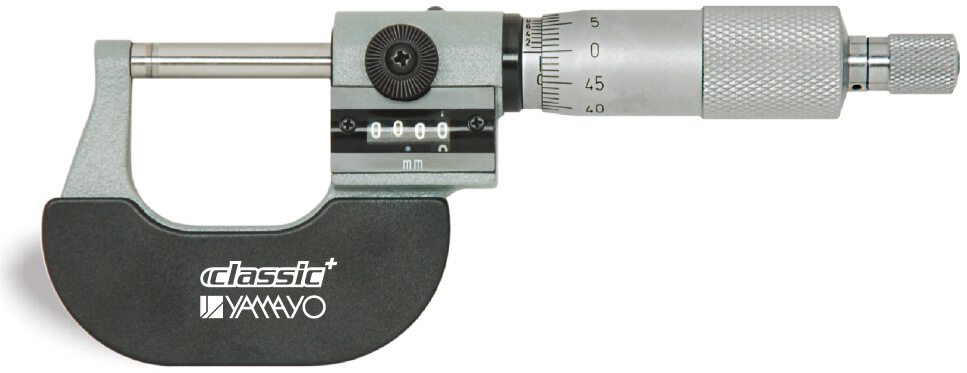 | Micrometers Digit Micrometers The Digit Micrometer is a precision mechanical measuring instrument designed for fast, accurate, and error-free external... View product → |
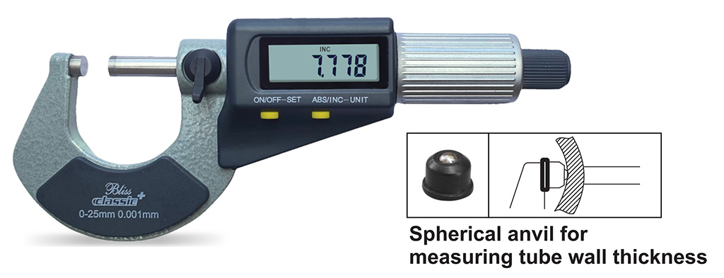 | Micrometers Digimatic Micrometers The Digimatic Micrometer is a high-precision digital measuring instrument designed for accurate external dimension measurement... View product → |
Frequently asked questions
What is the first check for a false digital micrometer reading?
Clean the measuring faces, close the micrometer correctly, equalise the instrument and part temperature, then check whether zero remains offset.
How can you distinguish operator technique from dirt, heat, and contact-force errors?
Repeat the measurement with clean faces, stable temperature, consistent ratchet or friction-thimble force, and correct alignment. A reading that changes with these controls points to technique or conditions rather than a fixed zero error.
Why does a Digimatic micrometer display become unstable?
Check battery condition, contamination, loose connections, electrical interference, and mechanical movement. Compare repeated readings and document when the display changes.
What repeated reading pattern indicates mechanical damage or geometry limits?
A consistent offset suggests zero or calibration error; variation at one spindle position suggests damage or contamination; increasing error across the range points to geometry, wear, or alignment limits.
What verification evidence should you request before choosing a workshop micrometer?
Request an instrument identification record, stated measurement range and resolution, verification date, reference standards, measurement results, uncertainty where provided, and traceability details.
Related product
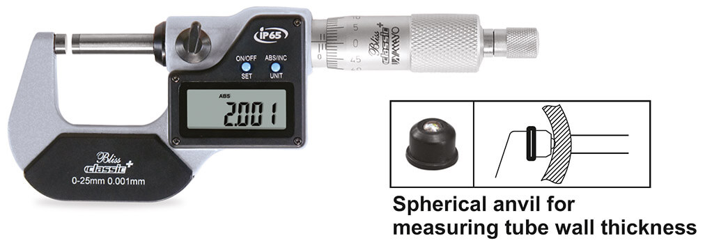 | Micrometers Digimatic Outside Micrometers The Digimatic Outside Micrometer is a high-precision digital measuring instrument designed for accurate external... View product → |