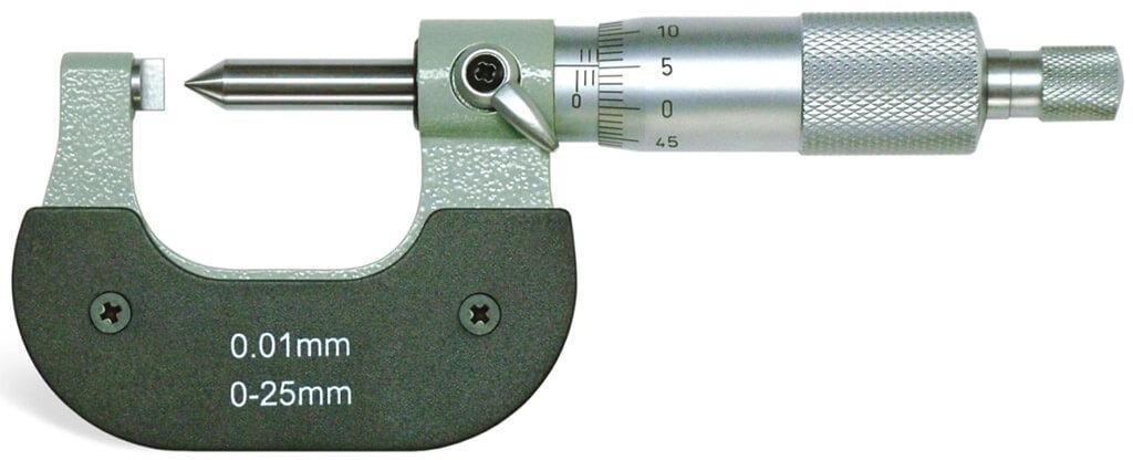
A point micrometer and a crimp height micrometer can show fine readings while contacting completely different parts of a component. Choose between them by matching the contact geometry, measurement axis, access, and specified inspection location to the automotive feature you need to control.
Key takeaways
- Use point micrometers for narrow rigid features, not terminal-barrel crimps.
- Measure conductor crimp height at the terminal drawing’s specified section.
- Keep open-barrel and closed-barrel crimp readings consistent with controlled positioning.
- Choose digital or mechanical operation based on inspection volume and recording needs.
Point micrometer comparison: which contact geometry fits the feature?
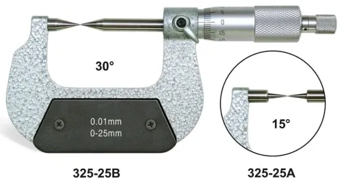
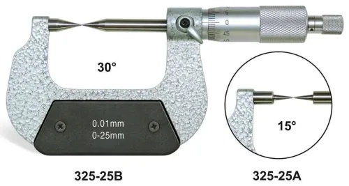
Choose a crimp-height micrometer for a terminal-barrel crimp; choose a point micrometer for a narrow groove, slot, drill web, or small shoulder on a rigid component. They are not interchangeable simply because both display 0.001 mm.
| Option | Point micrometer | Crimp-height micrometer |
|---|---|---|
| Contact geometry | Pointed anvil and spindle enter restricted features | Contacts seat on the defined terminal and conductor sides |
| Measurement axis | Follows the groove, recess, or shoulder being inspected | Follows the terminal drawing’s specified crimp-height axis |
| Access | Useful where flat anvils cannot reach | Provides clearance around the crimped barrel and wire |
| Range and resolution | Selected for the component’s feature size | Selected for the specified crimp-height range; resolution alone is insufficient |
| Repeatability | Depends on locating both points consistently | Depends on seating the terminal contacts without crushing the crimp |
| Best application | Machinery components with small external or recessed details | Open-barrel and closed-barrel automotive terminal crimps |
A pointed contact can land on a ridge, serration, strand, or seam instead of the defined crimp surfaces. The reading may repeat while still failing the terminal specification. In a point micrometer comparison, check contact shape, throat clearance, spindle travel, measuring force, and access to the specified section before comparing resolution.
For micrometers for machinery companies, a point model is often the practical general-purpose choice. If you are choosing a point micrometer or crimp height micrometer in Pune, match the contacts to a terminal drawing and reference sample; a calibration certificate confirms calibration, not application suitability.
Measure the conductor crimp at the specified section, not the insulation support
Read the terminal drawing or validated crimp application specification before taking the measurement. It identifies the conductor-crimp section, target crimp height, and acceptance limits; no universal automotive value applies to every terminal, wire size, or applicator.
Automotive inspectors use crimp height micrometers for this defined terminal dimension, not for the insulation support or as a simple outside-diameter check.
1. Identify the terminal part number, wire size, conductor material, and cavity or crimp position. Confirm that the terminal is seated in the specified orientation.
2. Locate the marked conductor-crimp section on the drawing. Keep the contacts away from the insulation wings, bellmouth, uncrimped barrel, and transition area, because each can produce a different reading.
3. Seat the dedicated anvil and spindle on the defined crimp surfaces. Hold the micrometer square to the terminal so the measuring axis follows the specified height direction.
4. Close the spindle using the instrument’s consistent force mechanism. Do not squeeze until the wings or barrel deform; crushing the terminal creates a false low value.
5. Record the reading with the terminal identification and measurement location. Repeat at the specified section when the process plan requires multiple readings.
A conventional pointed-anvil micrometer can land on a ridge, seam, or conductor strand and produce a repeatable but irrelevant result. The crimp height micrometer only verifies one dimension; confirm conductor brush, bellmouth, strand condition, insulation support, cross-section, and pull-out performance through the required inspection or qualification checks.
Handle open-barrel, closed-barrel and uneven crimps consistently
Measure at the terminal drawing’s defined conductor-crimp section, using the same orientation and contact surfaces every time. Do not measure the largest outside diameter, the insulation support, a bellmouth, or the transition into uncrimped barrel; each can produce a different value from the actual crimp height.
For open-barrel, closed-barrel, and irregular profiles, apply these rules:
- Open-barrel wings: seat the crimp-height micrometer on the specified conductor-crimp surfaces, not on the wing tips or the gap between wings.
- Closed-barrel crimps: keep the seam in the orientation shown by the terminal drawing. Do not let the anvil or spindle bridge the seam unless that drawing defines the seam as a measuring surface.
- Oval crimps: measure along the specified crimp-height axis, not across the widest outside dimension.
- Serrated crimps: use the defined flats or crest-to-base contact arrangement. Avoid choosing a tooth peak or valley because it gives a convenient reading.
- Tapered crimps: measure at the stated axial station, away from the taper, bellmouth, and uncrimped barrel.
- Uneven crimps: use the specified clock position or section and take additional readings only when the process document requires them. Do not average locations to hide a high or low result.
Crimp height micrometers for automotive terminals are designed to seat on these controlled surfaces. Use consistent force, keep the instrument square to the crimp, and stop before deforming the terminal. The acceptance limit comes from the terminal drawing or validated application specification, not from a universal value.
Digital or mechanical crimp height micrometer: what changes in daily inspection?
Choose the format around the inspection workflow, not the smallest displayed increment. A digital crimp height micrometer is easier to read at awkward angles and can send readings to a spreadsheet or quality record, but it is not inherently more accurate than a mechanical instrument.
| Option | Readability | Repeatability | Data handling | Operating risk |
|---|---|---|---|---|
| Digital crimp height micrometer | Clear numeric display reduces parallax and reading errors | Still depends on alignment, seating force and terminal condition | Data output, zeroing and unit conversion simplify records | Battery failure, accidental unit changes or an unverified zero can corrupt readings |
| Mechanical micrometer | Requires reading the sleeve and thimble correctly | Stable when the operator uses a defined force and position | Manual transcription adds entry errors | No battery or software risk, but misreading the scale remains possible |
For crimp height micrometers, automotive production gains more from a controlled method than from display resolution. Place the contacts squarely on the specified conductor-crimp section, use consistent force, and check repeatability with reference terminals; excessive force can compress strands or deform the barrel.
A digital crimp height micrometer is the practical choice when several inspectors need fast, legible readings and electronic records. Choose mechanical when the station needs rugged simplicity and disciplined manual recording.
Neither format proves crimp quality alone: confirm the terminal drawing’s limits and use cross-section, pull-out or tensile results, strand condition, bellmouth and insulation support checks where required.
Specify the instrument from the terminal drawing before buying in Pune
The terminal drawing must set the specification, not the catalogue title. It gives the target crimp height, tolerance, terminal family, wire size, and measurement section; there is no universal automotive value.
1. State the required range around the drawing’s crimp-height value, with enough travel to measure reference samples without working at the instrument’s limit. Specify resolution, accuracy, repeatability, anvil clearance, spindle travel, contact force, and access to the measurement axis. A 0.001 mm display does not make unsuitable contacts suitable.
2. Choose a crimp height micrometer for the terminal barrel. Choose a point micrometer for a narrow groove, slot, drill web, or restricted rigid feature. A point micrometer or crimp height micrometer in Pune should be selected from the feature geometry, not from resolution alone.
3. Request a calibration certificate identifying the instrument serial number, standards used, measured results, stated uncertainty, and calibration date. Prefer results from an ISO/IEC 17025-accredited laboratory, then record the calibration interval in your inspection procedure.
4. Test the proposed instrument on production-like reference terminals at the actual crimp-height values. Check alignment, contact seating, repeatability, and whether the contacts reach the specified section without crushing the terminal.
A digital crimp height micrometer improves reading and data capture, but it is not automatically more accurate than a mechanical model. Yamayo Instruments can help compare micrometers for machinery companies against the drawing and reference samples rather than supplying a generic model.
Related products
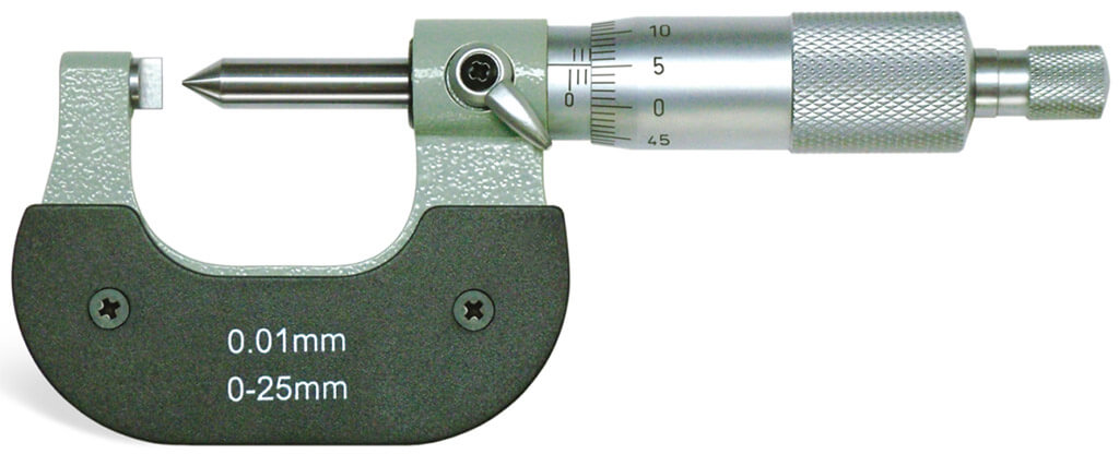 | Micrometers Crimp Height Micrometers The Crimp Height Micrometer is a specialized precision measuring instrument designed for accurate measurement of crimp... View product → |
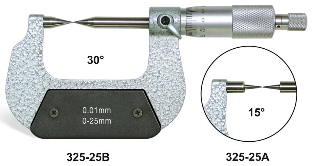 | Micrometers Point Outside Micrometers The Point Outside Micrometer is a specialized precision measuring instrument designed for measuring web thickness of... View product → |
Frequently asked questions
When should you use a point micrometer instead of a crimp height micrometer?
Use a point micrometer for narrow grooves, slots, drill webs, and small shoulders on rigid components. Use a crimp height micrometer for the specified height of a terminal-barrel crimp.
Where should you measure an automotive terminal crimp?
Measure the conductor crimp at the section identified on the terminal drawing. Do not measure the insulation support unless the drawing separately specifies that dimension.
How do you measure open-barrel, closed-barrel, and uneven crimps consistently?
Follow a fixed terminal orientation, contact the specified crimp section, avoid measuring the insulation support, and repeat readings at the drawing-defined locations.
What is the difference between a digital and mechanical crimp height micrometer?
A digital crimp height micrometer provides direct electronic readings and easier data recording. A mechanical model relies on a graduated sleeve and thimble, making technique and reading control more important.
What should you check before buying a micrometer in Pune?
Use the terminal drawing to confirm the crimp type, measurement section, required range, resolution, contact geometry, and inspection method before specifying the instrument.