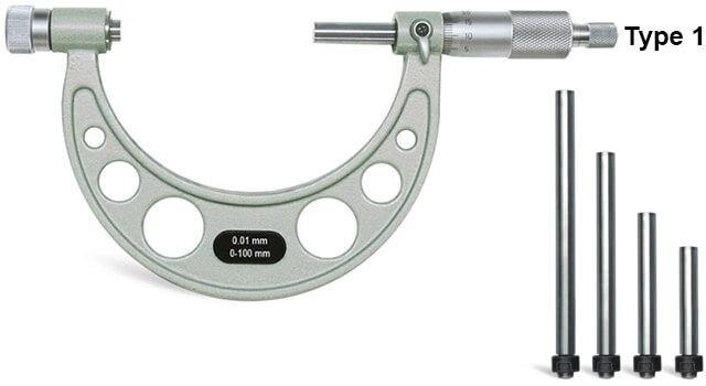
A screw measurement can fail before the reading is taken: a burr, angled contact, wrong anvil, or an unsuitable range can turn a service decision into a false pass or rejection. You will learn which screw dimensions an outside micrometer can measure, how to take and verify readings, and how to specify a dependable set for maintenance work in Pune.
Key takeaways
- Use an outside micrometer for opposing external screw surfaces.
- Match the micrometer range and anvil to the screw’s measured feature.
- Repeat measurements with clean faces, steady pressure, and consistent alignment.
- Verify zero, calibration, and anvil changes before releasing the instrument for maintenance work.
Match the screw characteristic to the right measuring method
Outside micrometer screw measurement suits dimensions defined by opposing external surfaces. Compare the measured value with the drawing’s nominal size and tolerance to identify wear, deformation, or an oversized replacement.
| Characteristic | Suitable method | What the reading tells you |
|---|---|---|
| Major diameter | Outside micrometer across thread crests | External thread envelope or major diameter only |
| Plain shank diameter | Outside micrometer on the cylindrical shank | Actual shank size; use this when the maintenance specification concerns shank diameter |
| Head thickness | Outside micrometer across the head | Axial head thickness |
| Head or shoulder diameter | Outside micrometer across the flat, accessible feature | Outside diameter, provided the anvil faces seat squarely |
| Pitch diameter | Thread micrometer with a V-anvil and cone spindle, or calibrated three-wire method | Effective thread size; an ordinary outside micrometer is not suitable |
Measuring across thread crests does not measure pitch, flank angle, thread form, or effective pitch diameter. If the specification names pitch diameter, use the thread-specific method rather than treating the major-diameter reading as a substitute.
Measure the cylindrical shank when that is the controlled characteristic. Damaged thread crests or a burr on the screw head can make a serviceable part appear oversized, so inspect the contact area and remove loose burrs before deciding that the screw has failed.
For wear checks, record the measured location, nominal size, tolerance, and deviation from nominal.
Take a repeatable screw measurement without damaging the reading
1. Clean the screw and the micrometer’s contact faces before measuring. Remove oil, chips, rust flakes, and loose dirt; debris trapped between the contacts can make a usable screw read oversized. Inspect the measuring area for burrs, flattened thread crests, or impact damage.
Do not accept a dimension from a damaged spot as the screw’s true size.
2. Select the specified location, then place the screw squarely between the anvil and spindle. Keep the frame and screw axis aligned; do not tilt the micrometer or touch the part at an angle.
For a shank measurement, use the cylindrical portion rather than a thread crest unless the required characteristic is the thread major diameter.
3. Close the spindle with the ratchet or friction thimble until its force-control mechanism operates. Stop there. Never force the spindle to overcome resistance, because excessive force can deform contact surfaces or produce a false reading. A ratchet improves force consistency but cannot correct dirt, misalignment, damaged anvils, or thermal expansion.
4. Take repeated readings at the same location and use the same ratchet or friction-thimble method for every comparison. Keep the screw and micrometer at a common temperature before an acceptance measurement.
Use 20 °C when the drawing, inspection procedure, or metrology system specifies that reference temperature, and never measure a screw immediately after machining, grinding, or service while it is hot.
Choose the interchangeable range, anvil, and performance specification
Choose a set whose frame and anvil place the screw dimension inside the working range, not at the frame limit. The micrometer interchangeable range is the combined capacity obtained by changing supplied anvils or rods; it is not the span available from one installed anvil.
Ask whether ISO 3611, ASME B89.1.13, JIS B 7502, or another named standard governs the instrument.
Require the quotation to state:
- Every individual range, including its minimum and maximum size, 25 mm or 1 inch increment where applicable, overlap with the adjacent range, anvil length, and resolution.
- The stated permissible error for each range, including the actual 275–300 mm range when relevant; a 0–25 mm specification does not automatically apply to it.
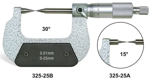
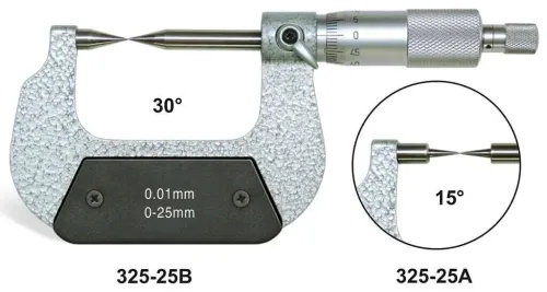
- Flat anvils for plain cylindrical shanks, or contact shapes designed for shoulders, grooves, and restricted features where a flat face cannot seat securely.
| Specification | What to compare | Selection rule |
|---|---|---|
| Resolution | Displayed or graduated increment, such as 0.001 mm | Choose the increment needed for the drawing and record |
| Permissible error | Maximum error stated for the actual measuring range | Do not treat a 0.001 mm display as 0.001 mm accuracy |
| Repeatability | Spread of repeated readings at the same location and force | Require a separately stated result or limit |
A set with finer resolution is not automatically more trustworthy. Confirm that the supplier’s performance data identifies the range, anvil configuration, permissible error, and repeatability separately.
Choose between a standard and Digimatic set, then verify every anvil change
Choose a conventional graduated set when battery-free operation and rugged workshop use matter most; choose a Digimatic set when quick reading, fewer transcription errors, or electronic data capture supports maintenance records.
| Readout | Strength | Trade-off |
|---|---|---|
| Conventional graduated | Robust, battery-free operation | Correct eye positioning and careful scale reading are essential |
| Digimatic | Easier readability, reduced transcription risk, possible data output | Depends on a battery and electronic components |
Neither format prevents errors from misalignment, dirt, thermal expansion, or excessive measuring force. A digital display does not make poor contact accurate.
After every anvil or rod change, clean the contact faces and locating shoulders. Inspect both for burrs, then seat the component fully before checking the indication.
- Perform a zero check with the correct setting standard or, where appropriate, the closed position. This confirms only the closed indication; it does not calibrate the interchangeable micrometer.
- Verify points across the working range using calibrated gauge blocks, setting standards, or length bars.
- Record the range checked, standard identification, result, date, operator, and instrument identification.
- Require a calibration certificate that states the applicable tolerance and measurement results. A certificate showing only a zero value is insufficient.
A Digimatic output helps only when your records system captures the reading with the instrument ID and range; otherwise, both formats still require disciplined recording.
Specify local support before buying in Pune
In Pune, judge a supplier by service readiness, not by a quoted range alone. Tell the maintenance micrometers supplier the screw sizes, measured characteristics, drawing tolerance, preferred units, required resolution, measuring-force control, anvil geometry, and whether readings support workshop comparison or formal acceptance inspection.
Ask for:
- A complete rod or anvil list, each individual range, adjacent-range overlap, supplied setting standards, component identification, replacement availability, and instructions for repeatable seating.
- Confirmation that recalibration is supported after an anvil or spindle assembly is replaced.
- Calibration documents naming the instrument, range, resolution, standards used, measurement results, uncertainty where applicable, and traceability.
Workshop comparison | Formal acceptance inspection Purpose | Detect wear or compare service parts | Accept or reject against a drawing Evidence | Repeatable readings and identified components | Recorded tolerance, calibration status, method, and environmental controls Supplier check | Replacement parts and seating guidance | Documented inspection method tied to the screw drawing or fastener specification
For interchangeable micrometers in Pune, require an ISO/IEC 17025 laboratory only when your quality system calls for it. Check that the current NABL scope covers the dimensional quantity and range; a logo alone proves nothing.
Yamayo Instruments can be considered when you need a Pune-based source for the set, replacement components, calibration coordination, and method-matching guidance. Confirm that support in writing before buying interchangeable outside micrometers for screw maintenance in Pune.
Frequently asked questions
Which screw characteristics can you measure with an outside micrometer?
Use an outside micrometer for dimensions defined by opposing external surfaces, such as screw shank diameter, thread crest diameter, shoulder diameter, or head thickness. Use thread wires, pitch micrometers, calipers, or gauges when the drawing specifies a different feature.
How do you take a repeatable outside micrometer screw measurement?
Clean the screw and measuring faces, align the micrometer squarely with the feature, close it using the ratchet or friction thimble, and take repeated readings at the same location. Compare the result with the drawing’s nominal size and tolerance.
How do you choose an interchangeable micrometer range and anvil?
Select a range that contains the screw’s nominal dimension without measuring at the mechanism’s limit. Choose an anvil that contacts the specified feature without touching threads, radii, burrs, or adjacent surfaces.
What must you verify after changing an interchangeable micrometer anvil?
Clean the contact surfaces, install the anvil correctly, check zero or reference position, and confirm the reading against a traceable standard within the required tolerance before measuring production parts.
What local support should you request when buying a maintenance micrometer in Pune?
Ask the supplier for range and anvil compatibility, calibration documentation, replacement-anvil availability, service arrangements, resolution details, and training or application support for your screw-maintenance measurements.