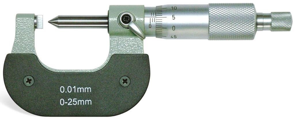
The correct instrument depends first on the dimension your terminal drawing controls, not on a large range or a 0.001 mm display. By the end, you will be able to specify the contact geometry, performance, calibration evidence and acceptance test needed to select a micrometer that works on your actual terminals and harnesses.
Key takeaways
- Measure the conductor barrel, excluding insulation wings and support.
- Seat contacts against the terminal before recording crimp height.
- Compare resolution, accuracy, repeatability, and jaw geometry—not display size alone.
- Require calibration evidence and a documented measurement method before production use.
Which crimp height must you measure?
Define the controlled dimension before comparing a digital crimp height micrometer in Pune. In most terminal specifications, crimp height is the distance from the bottom of the conductor-barrel crimp to the highest point of the formed conductor barrel. Exclude the insulation wings and insulation support.
| Measurement | Contact location | Confirm from |
|---|---|---|
| Conductor crimp height | Bottom of the conductor barrel to its highest formed point | Terminal drawing or crimp specification |
| Insulation crimp height | The formed insulation-support wings | Applicator setup sheet or terminal specification |
| Other terminal feature | The named feature and cross-section shown on the drawing | Wire-harness control plan |
Do not select a tool from its range alone; no universal crimp-height value exists. Record the terminal part number, conductor size, strand construction, applicator and tooling identifier, target value, and permitted tolerance.
- Ask whether the drawing also controls bellmouth, conductor brush, wire-end protrusion, exposed strands, terminal damage, insulation support, and pull-force or tensile performance.
- Ask any supplier offering a micrometer for crimp measurement how the anvils locate on the conductor barrel while excluding the insulation crimp, wire, wings, and adjacent features.
- Check that the measuring force will not mark soft plating or deform a marginal crimp.
A height reading is one dimensional check, not proof that the complete crimp is acceptable. Confirm the approved measurement location before taking readings.
How should the contacts reach the terminal?
Choose the contact geometry and access arrangement from the terminal’s actual cross-section, not from the nominal range of a micrometer for crimp measurement. Position the terminal squarely between the anvil and spindle at the specified cross-section.
| Contact option | Suitable feature | Check before selecting |
|---|---|---|
| Flat anvil | Broad, regular conductor barrel | Confirm it sits on the barrel without touching an edge or adjacent feature |
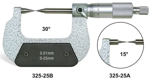
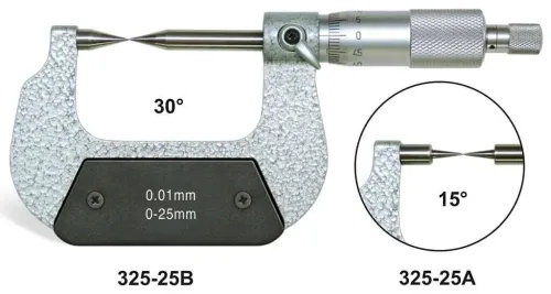
| Narrow or pointed contact | Wings, seams, serrations and tight measurement points | Confirm it reaches the formed barrel without catching a seam |
| Blade-style contact | Restricted gaps or narrow barrel surfaces | Confirm the blade passes through without crushing a thin wall |
| Ball or profiled contact | Curved barrels and unusual formed sections | Confirm the profile follows the specified contact location |
Keep both contacts on the formed conductor barrel. Do not touch the wire, catch an insulation wing, measure an edge or bridge an adjacent feature; each error can produce a convincing but invalid reading. Check the measuring force as well: repeated contact can mark soft plating or deform a marginal crimp.
For terminals installed on long wires or a harness, check jaw throat depth, spindle clearance and operator access. A bench instrument that handles a loose terminal can fail in production when the harness prevents square positioning.
Include representative samples with different barrel shapes, seams and insulation supports when comparing crimp height micrometer options. Verify that the contact passes the terminal without damage and that the reading location is visible and repeatable in the work instruction.
Which specifications separate a readable tool from an accurate one?
A 0.001 mm display does not mean ±0.001 mm accuracy. Choose range, resolution, accuracy and repeatability against the approved crimp tolerance, then request evidence across the working range rather than accepting resolution alone.
| Specification | What to request | Why it matters |
|---|---|---|
| Range and accuracy | Manufacturer’s accuracy and measurement uncertainty at several points across the range | A tool can perform well near zero and fail near its upper limit |
| Repeatability and force | Repeatability data, permitted measuring force and the conditions used for both | Hand-tightening can compress or shift a thin barrel |
| Force control | Ratchet or another controlled-force mechanism | Operators produce more comparable readings |
| Display and controls | Clear digits, inch/metric control, stable zero, and protection against mixed-unit or accidental-zero errors | A readable display does not prevent a wrong reading |
| Data capture | Repeatable digital interface or a controlled manual recording method | Digital output supports SPC only when capture is consistent |
Include the permitted force in the purchasing specification, especially where repeated contact could mark plating or deform a marginal crimp. Ask for crimp height micrometer options with force control, and state whether the terminal must remain electrically and mechanically serviceable after inspection.
For tight tolerances, allow the instrument, terminal and reference standard to reach the same temperature. Record conditions around 20 °C, the dimensional reference temperature defined by ISO 1. Before measurement, zero or reference-check the tool and verify at least one point within its working range; a zero-only check does not prove performance across the range.
Which measurement method is right for your line?
Choose the method that reaches the approved measurement location on the actual terminal, not the tool already sitting on your bench. A dedicated crimp height micrometer gives controlled contact and repeatability, but alternatives can work when their contact geometry matches the conductor barrel.
| Option | Strength | Limitation |
|---|---|---|
| Dedicated crimp height micrometer | Controlled contact and repeatable force | Less useful if its anvils cannot reach the harness |
| Standard outside micrometer | Works on broad barrels with clear access | Anvils must exclude insulation and wire |
| Point micrometer | Reaches narrow features or restricted barrels | Contact point can be difficult to position consistently |
| Caliper | Fast for screening | Lower contact control and repeatability for small tolerances |
| Optical comparator | Non-contact profile and seam inspection | Needs stable fixturing, interpretation and more operator time |
| Crimp-height fixture | Fast for one defined terminal family | Less flexible when part numbers change |
Before buying crimp height micrometers in Pune, test representative terminal-and-wire combinations, not only gauge blocks. Compare each tool with the approved reference method, repeat readings between operators, check access on the installed harness and confirm that it separates known-good crimps from out-of-target crimps.
Yamayo Instruments can help you examine contact geometry, working access, demonstrations and documented specifications, but accept the method only after the sample test passes. A fast fixture that cannot handle the next terminal change is not a flexible production solution.
Related product
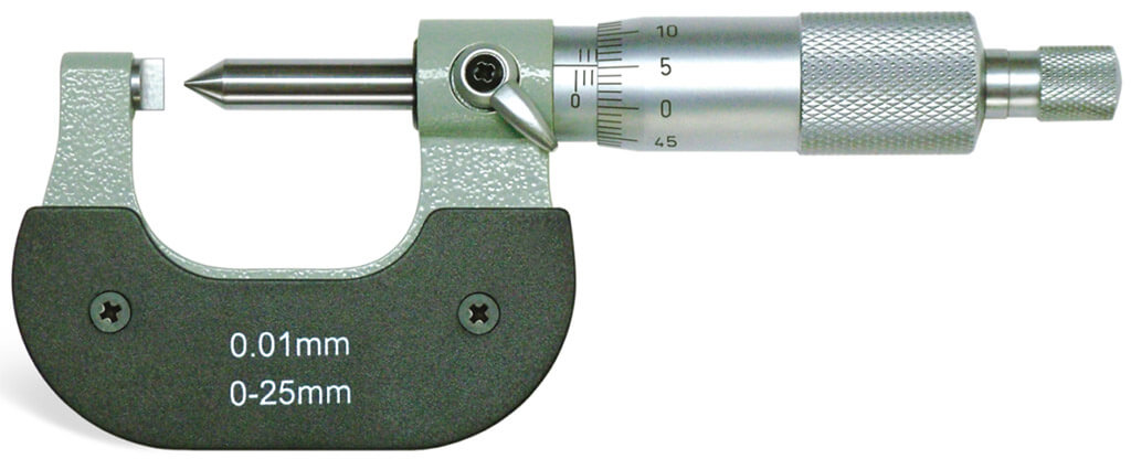 | Micrometers Crimp Height Micrometers The Crimp Height Micrometer is a specialized precision measuring instrument designed for accurate measurement of crimp... View product → |
What evidence should you require before putting the tool into service?
A calibration certificate alone does not qualify a digital crimp height micrometer in Pune for production. Require evidence that covers the instrument, the working range and the way operators will use it.
1. Request a certificate that names the instrument serial number, standards used, measured deviations, environmental conditions and measurement uncertainty. If accredited calibration is required, confirm that the laboratory’s ISO/IEC 17025 scope covers dimensional measurement and the required range. A generic calibration certificate is not equivalent.
2. Before each measurement session, close the contacts and zero the instrument, or reference-check it with a suitable certified standard. Verify one or more additional points within the working range. A certificate showing only a zero check does not establish performance across the crimp-height range.
3. Put the method into the work instruction. Specify terminal orientation, contact location, measuring force, zeroing method, temperature limits and data-recording steps. Record temperature when tolerances are tight, and allow the instrument, terminal and reference standard to equilibrate near the ISO 1 reference temperature of 20 °C.
4. Perform measurement-system analysis after installation. If gage repeatability and reproducibility are large compared with the crimp tolerance, apparent process variation may come from contact geometry, fixturing, operator technique or the instrument.
5. Requalify the method when the terminal, tooling or harness access changes. A new access condition can invalidate an otherwise acceptable measurement method.
Frequently asked questions
Which crimp height must you measure?
Measure from the bottom of the conductor-barrel crimp to the highest point of the formed conductor barrel. Exclude the insulation wings and insulation support.
How should the contacts reach the terminal?
Seat the micrometer contacts consistently against the defined bottom and highest point of the conductor barrel before recording the reading.
Which specifications separate a readable tool from an accurate one?
Compare resolution, stated accuracy, repeatability, contact or jaw geometry, measuring range, and calibration evidence.
Which measurement method is right for your line?
Choose the method that matches your terminal design, inspection frequency, operator workflow, and required measurement repeatability.
What evidence should you require before putting the tool into service?
Request calibration documentation, stated accuracy and resolution, traceability details, operating instructions, and a defined verification method.