A maintenance technician needs more than a number on a screen: the measuring faces must contact the part correctly, the zero must be established against a known reference, and temperature and contamination must be controlled. By the end, you will know how the measuring chain works, how to adjust and verify the instrument, and how to specify the right model for plant work in Pune.
Key takeaways
- Clean the measuring faces and workpiece before every micrometer check.
- Set zero with the spindle closed, then verify against a known standard.
- Let hot components cool before measuring, unless your procedure compensates for temperature.
- Choose calipers, bore gauges or depth tools when an outside micrometer cannot reach.
How the Adjustable Micrometer Produces a Digital Reading
The adjustable micrometers working process starts with clean, stable contact. Wipe the anvil, spindle face and workpiece with a lint-free cloth; one chip or oil film can add measurable error.
1. Close the spindle gently and check the display at zero. For a 25–50 mm micrometer, use its calibrated setting standard rather than forcing the faces together. Zero confirms the reference position, not accuracy across the range.
2. Open the spindle farther than the workpiece, place the shaft, pin, bushing or sleeve squarely between the anvil and spindle, then keep the instrument aligned with the measured diameter.
3. Turn the ratchet or friction thimble until it slips or maintains its defined friction. Do not tighten the main thimble against the part; excess force can deflect the frame, compress the workpiece or produce a false dimension.
4. Read the displayed value only after the contact settles. Confirm the selected unit, such as millimetres, and record the dimension with the instrument resolution shown on the display.
Mechanically, thimble rotation advances the spindle through a precision screw. A rotary encoder or linear scale detects that movement, and the electronic circuit converts it into the displayed dimension. The display resolution is the smallest increment shown; it is not the instrument’s accuracy.
Pitch error, alignment, worn faces and measuring force can still make a high-resolution reading wrong.
How to Set Zero and Verify an Outside Micrometer
Set zero only after the measuring faces are clean and the micrometer is at a known reference. A 0–25 mm model closes on its anvil and spindle; a 25–50 mm model requires its supplied calibrated setting standard because the faces cannot meet.
1. Wipe the anvil, spindle face and setting standard with a lint-free cloth. Remove chips and oil films that can create a false zero.
2. Bring the spindle gently onto the closed faces or standard using the ratchet or friction thimble. Engage the spindle lock, then check the display without turning the thimble.
3. If the reading is not zero, use the manufacturer’s adjustment key on the sleeve or frame adjustment, according to the instrument design. Keep contact pressure unchanged, unlock only as required, correct the reading, and recheck it after locking; forcing the adjustment can shift the reference.
4. Verify the setting at several calibrated gauge blocks or standards across the working range. Record indication error and repeatability, not just whether the display returns to zero.
A 0.001 mm resolution means the display changes in 0.001 mm steps; it does not promise 0.001 mm accuracy. Accuracy also depends on screw pitch, encoder or scale performance, frame rigidity, contact force, temperature, alignment and face condition.
Check the supplier’s maximum permissible error and calibration certificate, with ISO 3611 used as the relevant external-micrometer design reference. A zero pass cannot expose pitch or alignment error.
Using Micrometers on Shafts, Bushings and Hot Plant Components
A chip between the spindle and a shaft can create a false undersize reading, while excessive ratchet force can hide a worn journal. Clean the contact surfaces before every measurement, even when the component looks only oily.
- Wipe the anvil, spindle and workpiece with a lint-free cloth; remove abrasive dust, burrs and coolant film. Do not drag grit across the measuring faces.
- Check zero with the faces closed and confirm the display returns consistently. Before accepting a critical dimension, verify at several points across the range using calibrated gauge blocks or setting standards; check repeatability as well as indication error.
- Measure a shaft journal at several axial and angular positions. Record the largest variation instead of averaging away taper, ovality or a local wear groove.
- Measure a bushing or sleeve’s outside diameter with the micrometer. Use a bore gauge or internal micrometer for its bore; forcing an outside micrometer into the opening damages the instrument and proves nothing.
- Close with the ratchet or friction thimble until it slips consistently, then read the display without squeezing the frame.
Do not acceptance-test a recently machined or hot component immediately. Let both part and instrument reach near 20 °C; a 100 mm steel feature changes about 11.5 µm for a 10 °C change. IP65 resists dust and water jets, not immersion or steam cleaning, so wipe the instrument, protect battery contacts and store it dry.
Keep a known-good reference check for battery, encoder or display failures.
Choosing the Right Micrometer or a Different Measuring Tool
Choose the smallest range that contains the feature: use a 0–25 mm micrometer for a 18 mm shaft, not a 0–100 mm instrument. A shorter frame reduces handling error, while 25–50 mm suits a 32 mm journal.
Select 0.001 mm resolution for fine wear comparisons; do not call that accuracy unless the specification states maximum permissible error and repeatability.
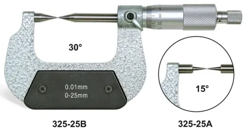
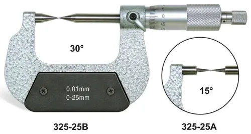
Use flat, parallel anvils for shaft diameters, pins and bushings. Ball or spherical anvils suit curved or thin-wall surfaces; blade or disc anvils reach narrow grooves and shoulders. The wrong face geometry touches an edge instead of the intended surface and produces a false diameter.
| Option | What it measures | When it applies |
|---|---|---|
| Digital outside micrometer | External diameter or thickness | Shafts, journals, sleeves, pins and close-tolerance acceptance checks |
| Digital caliper | Outside, inside, depth and step dimensions | Quick checks, larger features and dimensions where micrometre accuracy is unnecessary |
| Inside bore gauge | Internal diameter relative to a setting standard | Bushings, bearing housings and bores; use it when two-point access is impossible |
| NDT method | Cracks, voids or subsurface discontinuities | Use magnetic-particle testing on ferromagnetic parts, dye penetrant on surface-breaking defects, or ultrasonic testing for internal flaws |
Choose a caliper for speed, not for a tight fit decision. A bore gauge needs a calibrated setting ring or master; without that reference, its reading has no trustworthy zero. Select NDT when the question is “is the material damaged?” rather than “what is its dimension?”
What to Specify When Buying a Micrometer for Pune Plant Work
Specify the instrument by range, not by the word “digital.” Digital adjustable micrometers for plant maintenance in pune still have fixed spindle travel, such as 0–25 mm or 25–50 mm. Record resolution separately from maximum permissible error; a 0.001 mm display does not prove 1 µm accuracy.
Check these purchase points:
- Range, resolution, maximum permissible error, and repeatability across the working range
- IP rating for coolant, oil, and dust exposure; carbide or hardened measuring faces
- Ratchet or friction-thimble operation, zero adjustment, and the supplied setting standard
- Battery type, low-battery behaviour, data interface, compatible cable, and spare battery availability
- Calibration certificate, traceability, and whether calibration was performed by an ISO/IEC 17025-accredited laboratory
- Availability of replacement anvils, batteries, cables, and repair support in India
| Check | What to specify | Evidence to request |
|---|---|---|
| Temperature | Reference at 20 °C; allow the part and micrometer to stabilise | Measurement procedure stating temperature control |
| Data capture | USB, RS-232, wireless, or no output | Interface model, cable requirement, and software details |
| Verification | Multiple gauge-block points, zero, indication error, and repeatability | Calibration report showing readings, not only a zero statement |
A 100 mm steel feature changes about 11.5 µm over a 10 °C change, so do not accept a hot shaft measurement as a final dimension. Ask a micrometers supplier in pune to demonstrate the exact model, certificate, interface, and replacement plan; Yamayo Instruments can help compare those records against the instrument offered.
Related products
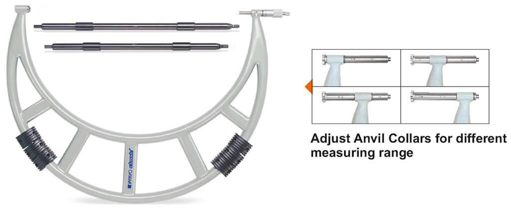
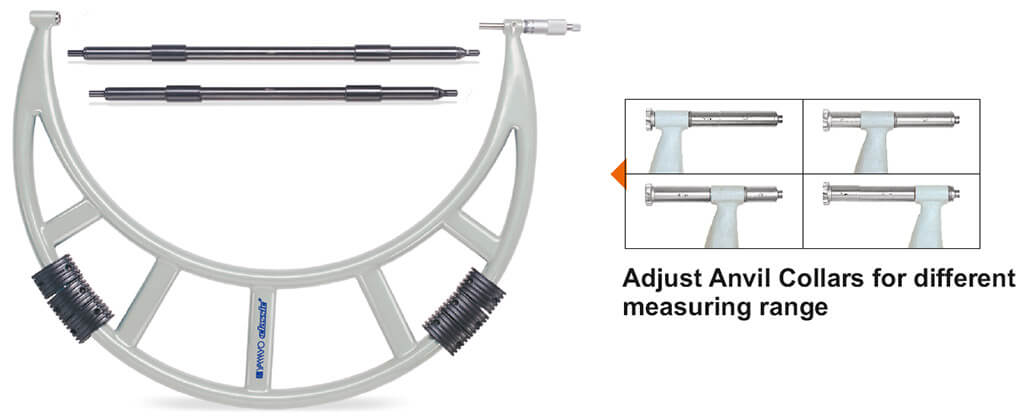 | Micrometers Adjustable Outside Micrometers Adjustable Outside Micrometers The Adjustable Outside Micrometer is a precision measuring instrument designed for accurate measurement of large... View product → |
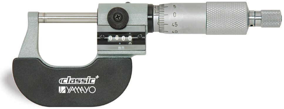 | Micrometers Digit Micrometers The Digit Micrometer is a precision mechanical measuring instrument designed for fast, accurate, and error-free external... View product → |
Frequently asked questions
How does a digital adjustable micrometer produce a reading?
The spindle advances through a precision screw, and an electronic scale converts its movement into a digital measurement.
How do you set zero and verify an outside micrometer?
Clean the anvil and spindle, close them with the ratchet, set the display to zero, then check a certified standard across the measuring range.
Can you measure hot plant components with a micrometer?
Measure after the component reaches a stable temperature. Thermal expansion can make a shaft read larger than its room-temperature size.
When should you choose a different measuring tool?
Use calipers for faster general checks, bore gauges for internal diameters, depth gauges for recesses, and thread micrometers for thread measurements.
What should you specify when buying a micrometer for Pune plant work?
Specify range, resolution, accuracy, measuring-face type, ratchet or friction thimble, protection rating, temperature conditions and calibration documentation.
Related products
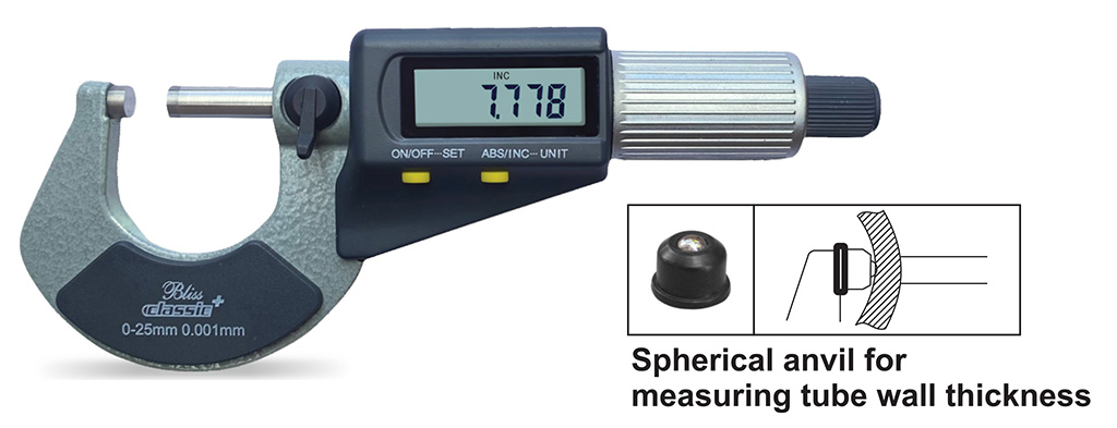 | Micrometers Digimatic Micrometers The Digimatic Micrometer is a high-precision digital measuring instrument designed for accurate external dimension measurement... View product → |
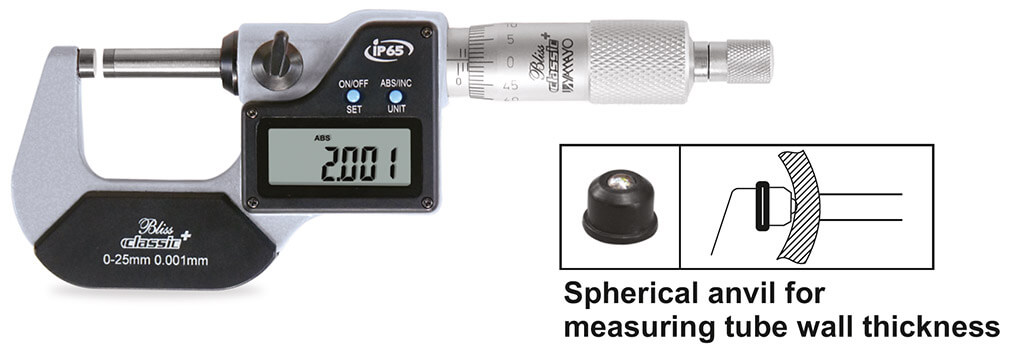 | Micrometers Digimatic Outside Micrometers The Digimatic Outside Micrometer is a high-precision digital measuring instrument designed for accurate external... View product → |
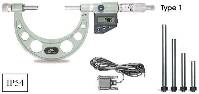 | Micrometers Digimatic Interchangeable Outside Micrometers Digimatic Interchangeable Outside Micrometers The Digimatic Interchangeable Outside Micrometer is a high-precision digital measuring instrument... View product → |
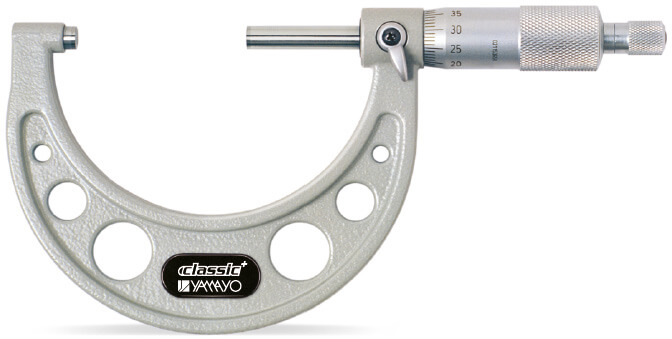 | Micrometers Outside Micrometers The Outside Micrometer is a precision measuring instrument designed for accurate external dimension measurement of components,... View product → |