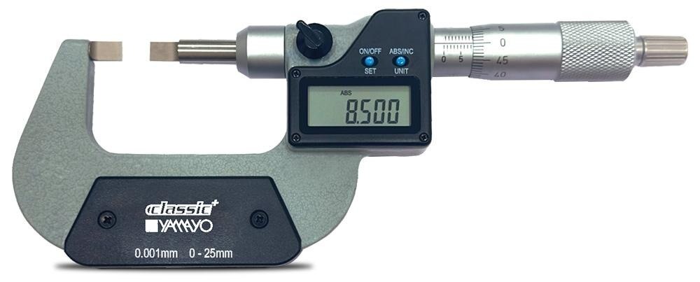
A blade micrometer converts thimble rotation into controlled spindle movement, then reports that movement through an encoder on the digital display. By following the screw mechanism from pitch to reading, you can select the right blade geometry, measure a narrow feature without alignment errors, and judge whether the displayed value is trustworthy.
Key takeaways
- One screw revolution advances the spindle by exactly one screw pitch.
- Resolution is not the same as accuracy or repeatability.
- Clean both blades and the workpiece before taking a reading.
- Keep the blades parallel to the groove walls to avoid false dimensions.
How the screw converts thimble rotation into blade movement
A 0.5 mm pitch screw advances the spindle 0.5 mm during one complete thimble revolution and 0.25 mm during half a revolution. This is the core of the blade micrometer screw mechanism: axial travel equals screw pitch multiplied by the number of revolutions.
Turning the thimble rotates the precision helical screw, which moves the spindle or moving blade along its axis toward the fixed blade.
- Frame: Supports the instrument and holds the fixed anvil or blade in position.
- Blades: The fixed and moving contact faces touch the workpiece and define the measured distance at one local cross-section.
- Thimble: Supplies the hand rotation that turns the screw.
- Ratchet or friction drive: Controls contact force after the blades touch; turning harder can deform a thin workpiece or create inconsistent readings.
- Lock: Holds the spindle position for checking or recording a reading. It cannot correct tilted blades or poor alignment.
- Encoder: Detects spindle displacement and converts that movement into an electronic signal.
- Display: Shows the displacement reported by the encoder; it does not replace the screw or create measuring motion.
- Battery: Powers the encoder electronics and display, not the mechanical movement.
In digital blade micrometers, separate these functions during fault diagnosis. A dead display points toward the battery or electronics; an incorrect movement points toward the screw, spindle, or encoder; unstable readings point toward force control, blade damage, contamination, or alignment. Zeroing changes an offset only and does not repair these faults.
Why pitch, resolution, accuracy, and repeatability are different
Screw pitch tells you how far the spindle travels for a given rotation; it does not define the instrument’s accuracy or repeatability. A conventional metric micrometer with a 0.5 mm pitch and 50 thimble divisions moves 0.01 mm per division.
A Digimatic instrument can display 0.001 mm, but three decimal places do not prove 0.001 mm accuracy.
| Concept | Meaning | Limitation |
|---|---|---|
| Resolution | Smallest displayed increment | Does not show closeness to the true dimension |
| Accuracy | Permitted difference from a reference value | Does not guarantee repeated readings will agree |
| Repeatability | Agreement between repeated readings under the same conditions | Does not prove either reading is correct |
In a Digimatic blade micrometer process, check the model specification for accuracy, resolution, measuring force, and permitted environmental conditions. Screw wear, spindle play, damaged blades, contamination, temperature, and inconsistent ratchet force can reduce repeatability even when the display appears stable.
Digital zeroing applies an offset; it does not calibrate screw pitch, encoder performance, blade parallelism, or measuring force. If a zero check or reference standard check fails, do not hide the error by resetting zero: follow your calibration procedure and remove the instrument from service when required.
At tight tolerances, let the part and instrument reach the 20 °C reference temperature. A warm part held in your hand can expand during measurement, while hand heat can warm the instrument. These controls matter for digital blade micrometers because a stable-looking reading can still represent the wrong dimension.
Micrometer measurement steps for a clean, aligned reading
For a groove, keyway, spline, or narrow slot, clean the contacts and align the blades before trusting the display. These micrometer measurement steps prevent a dirt particle or tilted setup from becoming a false dimension.
1. Wipe both blade faces and the workpiece with a suitable lint-free material. Remove oil, abrasive particles, plating flakes, and loose debris, but do not remove material that belongs to the specified feature.
2. Inspect both thin blades for nicks, burrs, bending, and other damage. Close the instrument gently to check zero, or use the manufacturer’s specified zero-setting method when required.
3. Select the correct unit and resolution before measuring. Place the blades at the intended cross-section, using the feature datum and geometry to align the spindle axis with the dimension between the surfaces.
4. Keep the thin blades clear of the slot or groove side walls. Side contact produces a high or unstable reading, while a tilted setup introduces cosine error and measures a longer path than the intended distance.
5. Do not measure across a chamfer, radius, burr, damaged edge, or dirt particle. Close the instrument with the ratchet or friction drive until it slips or reaches its controlled force; never tighten the thimble by hand after contact.
6. Read the display and record the value, location, and orientation. Slightly reposition the instrument and repeat the reading without changing the measuring force.
A material change after repositioning indicates alignment, contamination, or feature-form problems, not useful precision. A Digimatic blade micrometer process measures one local cross-section; inspect multiple locations or angles when uniformity matters, and do not rely on the lock to rescue a tilted setup.
How to find the true groove dimension without tilting the blades
The true groove dimension is the repeatable maximum or minimum found by controlled rocking, not merely the last stable digits on the display.
1. Use the feature datum and geometry to align the blade faces normal to the surfaces defining the dimension. Keep the blades clear of side walls, burrs, dirt particles, plating ridges, chamfers, and damaged edges. A raised defect can shift a narrow-blade reading significantly.
2. Apply light, consistent ratchet or friction-drive force. Rock the micrometer through a small, controlled angle while watching the display. Find the repeatable maximum or minimum required by the drawing, then approach that position again from both directions. A value that changes materially indicates misalignment, contamination, a burr, or feature-form error.
3. Repeat these micrometer measurement steps at several axial locations along the groove. If uniformity around a shaft or spline matters, measure at multiple angular positions as well. Digital blade micrometers measure one local cross-section; they do not prove that the groove is uniform, the shaft is round, or the part has no internal defect.
4. Record the location, orientation, temperature, and repeated values with the result. Allow the part and instrument to stabilise near the 20 °C reference temperature when tolerance is tight. Use a gauge, optical system, additional dimensional checks, or an appropriate non-destructive-testing method for questions a local blade reading cannot answer.
How to choose the blade and instrument for the feature
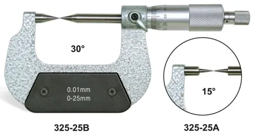
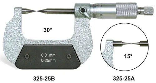
Choose a blade thickness and width that enter the slot or groove with clearance. The blade reach must pass any shoulder before the contact faces reach the measuring surfaces. Match the blade geometry to the feature bottom and side access; contact with a radius or chamfer measures the wrong dimension.
| Instrument | Best fit | Main limitation |
|---|---|---|
| Standard outside micrometer | Broad external faces that meet the anvils squarely | Cannot reliably reach narrow grooves or recessed surfaces |
| Blade micrometer | Slots, grooves, keyways, and thin shoulders | Side-wall contact or insufficient reach creates unstable readings |
| Point micrometer | A small recess requiring a pointed contact | The point can damage edges or misread a rounded feature |
| Depth micrometer | A dimension from a reference surface down into a recess | Requires a stable reference surface and proper seating |
| Caliper | Fast checks where the jaws can access the feature | Lower control and force stability than a micrometer |
For how a screw works with Digimatic blade micrometers in Pune, remember that fit matters more than extra display digits. Compare measuring range, blade width, thickness and reach, resolution, accuracy, ratchet or friction control, protection rating, data-output interface, and calibration documentation when sourcing digital blade micrometers.
Digital and Digimatic are not interchangeable: Digimatic normally identifies a defined digital measurement and data-interface family, while a generic digital instrument may have another output or none. Yamayo Instruments can help Pune-area businesses match those specifications to the feature drawing and inspection tolerance rather than selecting by resolution alone.
Related product
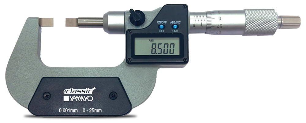 | Micrometers Digimatic Blade Micrometers The Digimatic Blade Micrometer is a precision digital measuring instrument specially designed for measuring groove... View product → |
Frequently asked questions
How does the screw work in a Digimatic blade micrometer?
The screw converts thimble rotation into axial spindle movement. With a 0.5 mm pitch, one complete revolution moves the spindle 0.5 mm and half a revolution moves it 0.25 mm.
What is the difference between pitch, resolution, accuracy, and repeatability?
Pitch is spindle travel per screw revolution. Resolution is the smallest displayed increment. Accuracy is closeness to the reference dimension, while repeatability is the consistency of repeated readings.
What are the correct micrometer measurement steps?
Clean the contact surfaces and workpiece, zero the instrument, place the blades squarely on the feature, apply consistent measuring force, and record the stable digital reading.
How do you measure a groove without tilting the blades?
Align the blade faces parallel with the groove walls and perpendicular to the groove length. Rock the micrometer gently to find the consistent minimum or maximum reading required by the feature.
How do you choose a blade micrometer for a feature?
Match the blade width, thickness, reach, measuring range, resolution, and contact shape to the groove or recess. Choose a narrower blade when surrounding shoulders restrict access.