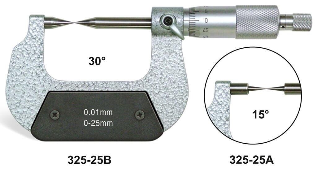
Choose the contact geometry from the feature on the drawing, not from the instrument’s displayed resolution or nominal measuring range. By the end, you will be able to select blade or point contacts, define a repeatable production method, compare alternatives, and request calibration and service evidence before buying.
Key takeaways
- Match blade thickness and width to the groove before choosing a measuring range.
- Control contact pressure, seating, temperature, and zero checks across every shift.
- Compare resolution with accuracy, calibration evidence, durability, and total inspection time.
- Ask Pune suppliers to prove geometry, standards, accessories, and service support in writing.
Match the contact geometry to the feature you must measure
Choose a digital blade micrometer for a narrow external groove, keyway, spline, or recessed shoulder only when its blade thickness and width enter the feature, reach the bottom or specified flank, and clear adjacent shoulders. Its nominal range, such as 0–25 mm, does not prove that it fits.
A groove diameter and groove width are different measurements. A blade seated at the bottom can measure diameter; opposed contacts placed against the side walls measure width. Confirm the drawing’s datum and contact direction before reading either value.
| Instrument | Contact geometry | Best fit |
|---|---|---|
| Digital blade micrometer | Thin, flat blade faces | Narrow external grooves, stepped shoulders, keyways, and splines where the blade seats fully |
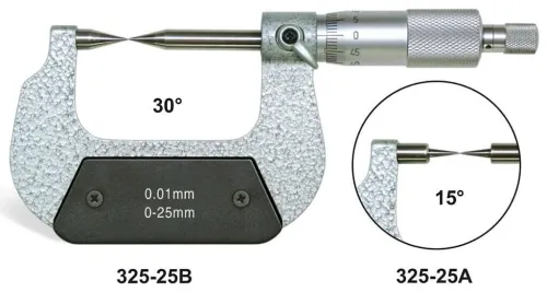
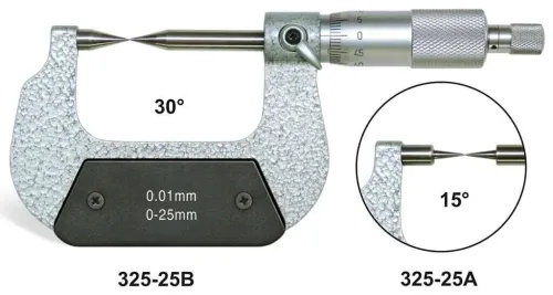
| Point micrometer | Pointed or conical contacts | Drill web thickness, narrow slots, and a defined local wall point |
| Standard outside micrometer | Broad, flat contacts | Accessible external dimensions without restricted shoulders |
Pointed or conical contacts suit a defined local point when the included angle and point radius match the drawing method. A sharp point is unsuitable for soft tubing or sheet if it indents the surface or contacts curvature inconsistently.
Before choosing blade micrometers in Pune, record:
- Minimum groove width and depth
- Corner radius and shoulder clearance
- Access direction and required reach
- Contact-face shape
- Whether the result is groove diameter, width, or local wall thickness
For blade micrometers in Pune, specify the geometry, not just the range. A digital blade micrometer that cannot seat without touching a shoulder will produce a precise answer to the wrong question.
Build a production method that gives the same result on every shift
Set one measurement method and train every shift to follow it. A point micrometer for production gives consistent results only when the contact location, orientation, and force are controlled.
- Let the part and instrument equalise to the reference temperature.
- Remove coolant, chips, and dirt from the feature and contact tips.
- Inspect the feature for burrs; remove or reject the part if a burr changes the surface.
- Close the micrometer gently and verify zero before measuring.
- Align the spindle and anvil normal to the intended surfaces, not at an angle.
- Turn the ratchet or friction thimble until its defined contact action is complete; do not add hand force.
- Confirm that the digital blade micrometer blade or point reaches the specified surfaces without touching a shoulder, groove wall, taper, or adjacent radius.
Use a fixed feature location and orientation. For a groove, confirm whether the blade contacts the bottom for diameter or the opposed walls for width; do not confuse either result with drill-web thickness. A sharp point can indent soft tubing or sheet. Excessive force, angled contact, burrs, contaminated tips, and worn contacts create false readings.
Repeat readings on the same part and across parts. Record whether each value is nominal, maximum wall thickness, or minimum wall thickness.
Keep a production record containing:
- Operator
- Part number
- Feature location and orientation
- Instrument ID
- Reading and result type
- Temperature or part condition
- Disposition: accepted, reworked, or rejected
Compare resolution, accuracy, calibration, and shop-floor reliability
A 0.001 mm display resolution only shows the increment reported, not the truth of the reading. Compare the manufacturer’s accuracy, repeatability, hysteresis, and maximum permissible error with the product tolerance; “precision” alone proves nothing. A 0–25 mm range does not establish blade reach or point alignment.
| Specification | What to compare | Decision |
|---|---|---|
| Resolution | Display increment versus tolerance | Do not accept fine digits as accuracy |
| Accuracy and maximum permissible error | Stated error across the range | Check the allowed measurement error |
| Repeatability and hysteresis | Repeated closing and approach directions | Reject unstable or direction-dependent readings |
| Process capability | Measurement variation versus process tolerance | Confirm the method can control production |
Before buying digital blade micrometers, verify:
- Zero across the intended range
- Contact alignment and spindle movement
- Ratchet operation and display stability
- Tip wear, damage, and contamination
- Readings against suitable traceable reference standards
Ask for an ISO 17025 calibration certificate only when the supplier can provide it, with the traceability statement, reference-standard identification, results, reported uncertainty, and calibration date. Set the calibration interval from use and risk, then define containment, impact review, and reinspection for an out-of-tolerance result.
Micrometer selection for manufacturing must control conditions: calibration is at 20 °C, so allow thermal equalisation before measurement. Remove coolant and chips, store the instrument clean and protected from drops, and check battery life and display readability. IP54 or IP65 limits protection to specified test conditions; neither rating approves every coolant, washdown process, or immersion.
Choose the inspection role and compare the total production cost
Put a point micrometer for production on a control plan only when the drawing defines a repeatable local thickness or narrow feature. It cannot replace inspection of a complete profile, runout, taper, or form error.
Use a dedicated, stable method for first-off approval and in-process checks. A 100 percent check must include cycle time, operator training, contact wear, and a controlled force procedure. Final audit sampling can justify one shared specialist instrument only when access, booking, calibration status, and availability are controlled across shifts.
| Option | Access and speed | Automation, coverage, and operator dependence |
|---|---|---|
| Digital blade micrometer | Reaches narrow external grooves quickly; needs correct blade fit and alignment | Local repeatability; manual placement and force |
| Point micrometer | Reaches a defined point, web, or narrow slot; slower to align | Local repeatability; sensitive to tip wear and surface condition |
| Standard outside micrometer | Stable on broad external faces; fast | Strong local control, limited recessed access |
| Vernier micrometer | Same access limits; slower reading | No battery or data output; transcription risk |
| Blade caliper | Fast access to open grooves | Lower contact stability and repeatability |
| Optical comparator | Slower setup; broad profile visibility | Measures profile and form with less contact dependence |
| Air gauge | Very fast in dedicated production fixtures | High repeatability and automation; needs tooling and air supply |
| CMM | Slowest for routine checks | Highest profile coverage; programming and skilled operation required |
Compare total cost: purchase price, calibration, batteries, training, data entry, contact replacement, and downtime. Sharing one tool adds queue time and missed checks. Treat digital output as procurement: confirm the port, cable or receiver, data format, SPC compatibility, and controls that block transcription and duplicate records. This is essential to micrometer selection for manufacturing.
Specify the quotation so a Pune supplier can prove the instrument fits
Send the feature evidence with the request, not just “digital blade micrometer in Pune” or “point micrometer for production.” A nominal 0–25 mm range does not prove that the contact reaches the surface or clears the shoulder.
1. State the metric or inch scale, measuring range, resolution, accuracy, repeatability, blade thickness and width, or point radius and included angle. Add reach, contact orientation, ratchet or friction thimble, display requirements, output connectivity, environmental conditions, quantity, and intended inspection role.
2. Attach the drawing or a sketch. Mark groove width, depth, corner radius, shoulder clearance, drill-web location, tolerance, access direction, and whether the required result is a maximum, minimum, or nominal value. This prevents a repeatable reading at the wrong location.
3. Ask for a demonstration on an equivalent feature. Require confirmation that the blade or point reaches the specified surfaces without bridging the groove or touching adjacent geometry, shoulders, or radii. Request delivery date, stock availability, calibration support, replacement contact parts, battery and service arrangements, and handling instructions.
4. For blade micrometers in Pune, ask the supplier to explain how blade thickness, width, and reach suit your drawing. For pointed contacts, confirm that the radius and angle will not indent soft tubing or sheet.
Yamayo Instruments can support a geometry-led quotation and demonstration in Pune; verify model-specific calibration evidence, service capability, lead time, and documentation before purchase or customer-audit use.
Related products
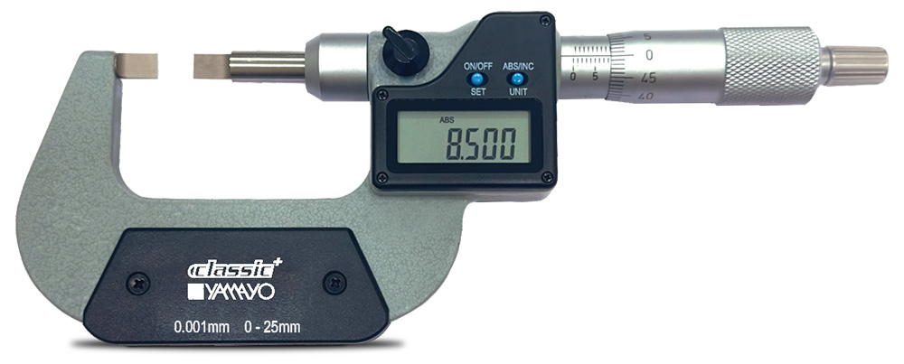 | Micrometers Digimatic Blade Micrometers The Digimatic Blade Micrometer is a precision digital measuring instrument specially designed for measuring groove... View product → |
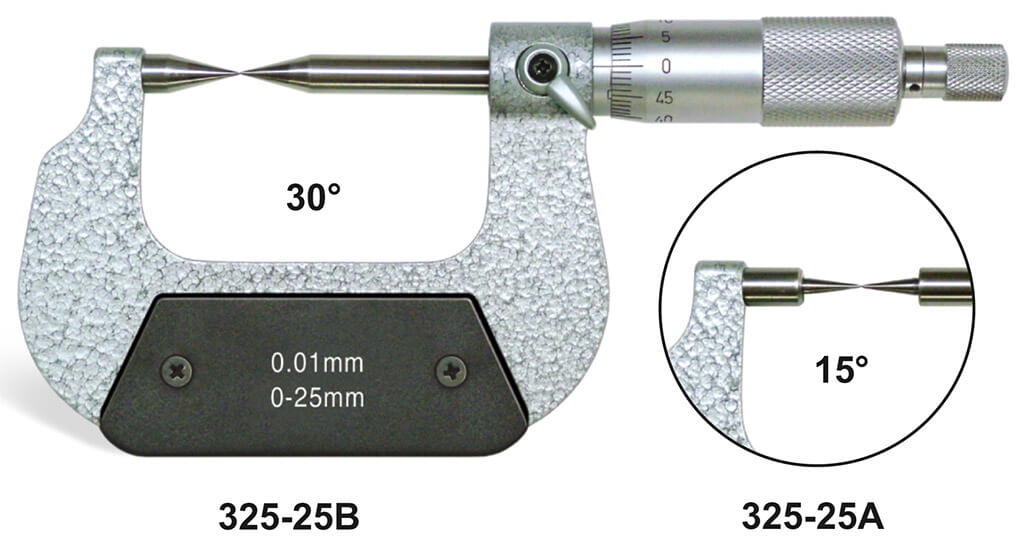 | Micrometers Point Outside Micrometers The Point Outside Micrometer is a specialized precision measuring instrument designed for measuring web thickness of... View product → |
Frequently asked questions
When should you choose a digital blade micrometer instead of a point micrometer?
Choose a digital blade micrometer for narrow external grooves, keyways, splines, or recessed shoulders when its blade enters the feature and reaches the required measuring surface. Choose a point micrometer when pointed anvils provide better access or contact at a small recess, flank, or radius.
Does a 0–25 mm micrometer range prove that the instrument fits the part?
No. Check blade or point thickness, width, reach, anvil shape, clearance from adjacent shoulders, and whether the contacts reach the specified flank or groove bottom.
How do you get the same production result on every shift?
Document the measurement direction, seating position, contact pressure, temperature conditions, zero check, reference standard, cleaning method, and acceptance limit. Train each shift to follow the same work instruction.
What should you compare besides micrometer resolution?
Compare accuracy across the working range, calibration traceability, repeatability, contact geometry, protection from coolant and chips, display readability, battery arrangements, and the time required to inspect each part.
What information should you include in a quotation request to a Pune supplier?
Provide the feature drawing, nominal size and tolerance, groove or shoulder dimensions, required contact reach, production volume, measurement environment, accuracy requirement, calibration documentation, accessories, and service expectations.
Related products
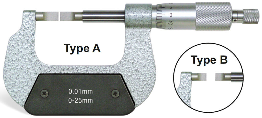 | Micrometers Blade Outside Micrometer The Blade Outside Micrometer is a specialized precision measuring instrument designed for measuring groove diameters, shaft... View product → |
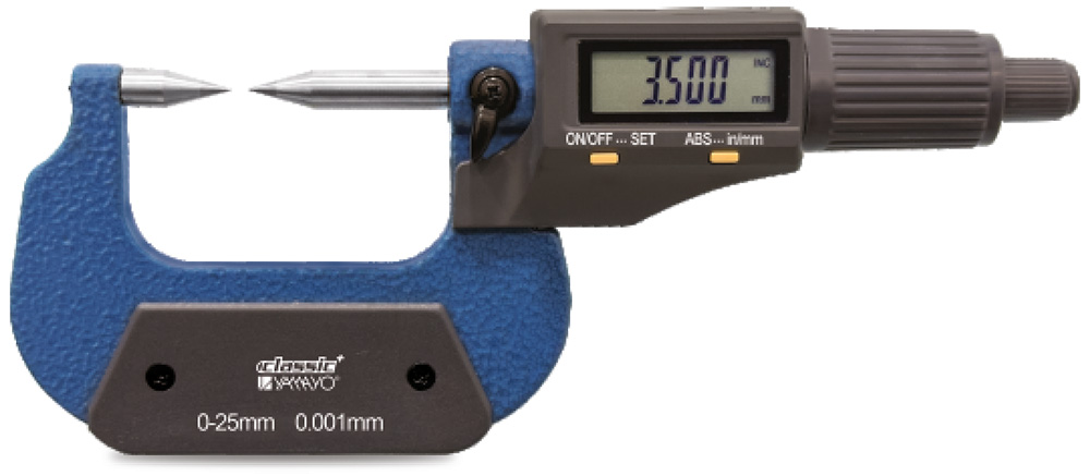 | Micrometers Digimatic Point Outside Micrometer Digimatic Point Outside Micrometer The Digimatic Point Outside Micrometer is a high-precision digital measuring instrument specifically designed for... View product → |