A production-part reading is only useful when the part, jaws, alignment, force, temperature, and instrument capability are controlled. By following a repeatable sequence, you can measure outside features, bores, depths, and shoulders while recognising when a carbide-jaw caliper is not suitable for the tolerance or surface.
Key takeaways
- Clean burrs, chips, oil, and abrasive particles before measuring.
- Seat jaws squarely without forcing them against the part.
- Use depth and step faces that match the feature geometry.
- Carbide resists jaw wear but cannot fix contamination or damaged inserts.
Prepare the caliper and part before taking a reading
A reliable reading begins with inspection, not with the display. Understanding how digital calipers with carbide jaws measure parts requires removing burrs, chips, abrasive particles, and oil from both the workpiece and measuring faces; carbide resists wear but cannot correct contamination or a damaged insert.
- Inspect the part and jaws under good lighting. Reject the reading if you find a raised burr, dent, embedded particle, loose jaw, or chipped carbide face.
- Wipe the outside, inside, or depth feature and both jaw faces with a clean, lint-free cloth. Do not drag grit across a finished surface.
- Close the jaws gently, confirm that the faces meet without a visible gap, and zero the caliper at the position used for measurement. Re-zero if the display changes after opening and closing.
- Select the correct contact point: outside jaws for an external size, inside jaws for a bore or slot, or the depth rod for a recess. Keep the selected faces away from chamfers unless the drawing defines the chamfer.
- Place the part squarely and align the caliper with the measured axis. Use light, repeatable contact pressure; squeezing can deflect thin walls, tilt the jaws, or mark soft material.
- Seat the jaws on the intended feature, rock the caliper gently when locating the maximum outside size, then stop when the reading stabilises. This carbide jaw caliper operation is the core of the digital caliper measurement process.
Record the displayed value with units, part number, feature, instrument ID, and measurement time. Include the operator or inspection lot when traceability is required.
Measure outside and inside features without creating false dimensions
False dimensions usually come from alignment and force, not from the digital display. Keep the outside jaws square to the measured axis, and find the feature’s true maximum dimension rather than accepting the first contact.
1. Place the outside jaws on the intended faces and apply only enough pressure to seat them. On a round or irregular part, rock the caliper slightly through the contact position and record the largest stable reading; a tilted caliper introduces cosine-related error.
2. Do not squeeze thin walls, flexible components, or sharp edges. Excess force can deflect the part, spread the jaws, mark the surface, or produce a smaller or larger value than light, repeatable contact.
3. For an inside measurement, insert the narrow carbide faces fully into the feature and open them square to its axis. Rock the caliper gently to find the largest stable bore reading; for a slot or recess, keep both faces parallel to the opposing walls.
4. Keep the inside jaws away from a chamfer, radius, burr, or tapered entry. Contact on a chamfer measures a false location rather than the intended internal diameter or width.
Carbide resists wear on rough, cast, forged, or coated production surfaces, but it can mark soft aluminium, plastic, paint, or sealing faces. Use a non-marring gauge when the contact surface must remain undamaged. That discipline is how digital calipers with carbide jaws measure parts consistently.
Check depths and steps against the actual feature geometry
A depth value is valid only when the caliper references the same surfaces that define the feature. Use the digital caliper measurement process to clean the part and contacts, close the jaws gently, zero at the measuring position, and select the depth rod or step faces that match the geometry.
1. For a recess or blind bore, place the caliper base flat on the reference face. Keep the depth rod aligned with the feature axis, then advance it until it contacts the true bottom with light, consistent pressure. A rod touching a chamfer, radius, or sloped bottom gives a shorter or unstable reading.
2. For a through-bore with a counterbore, identify which surface is the datum and which shoulder is the target. Seat the base on the datum face and ensure the rod reaches the intended shoulder rather than the bore entrance or a chamfer.
3. For an external shoulder or step, use the step faces: seat the fixed step face against the lower plane and the opposing step face against the higher plane. Keep both faces fully seated and the caliper square; rocking it changes the measured height.
4. Repeat the reading at several positions when the bottom or shoulder is uneven. Record the value only after the display remains stable. Good carbide jaw caliper operation improves contact-face wear resistance, not alignment; use a depth micrometer, height gauge, or CMM when geometry prevents reliable seating.
Understand what carbide improves—and what it cannot correct
Carbide inserts keep the measuring faces from wearing quickly when jaws repeatedly contact rough, abrasive, cast, forged, or coated surfaces. That preserves contact geometry and repeatability longer than ordinary hardened steel faces, but it does not make the beam, slider, jaw guides, or carbide immune to impact and wear.
Clean the part and jaws anyway. A chip, raised burr, embedded abrasive grain, or chipped insert can create a repeatable false dimension. Use only enough force to seat the jaws: excess force can deflect a thin wall, spread or tilt the jaws, mark a soft finish, or make the reading differ from light contact.
Treat a caliper as unsuitable when:
- Jaw, beam, or slider wear creates play, poor parallelism, or inconsistent repeat readings.
- The part is thin, flexible, hot, or cold enough to change size during the check; allow the part and instrument to reach the drawing’s reference temperature, commonly 20 °C.
- The required measurement depends on controlled force, such as a delicate finish, tight fit, or flexible edge.
- The display resolution is finer than the instrument’s stated accuracy, repeatability, and calibration uncertainty justify.
- The drawing tolerance is narrow relative to that total measurement uncertainty.
This is the practical limit of how digital calipers with carbide jaws measure parts: they suit comparative checks and broad tolerances, not precision bores or high-accuracy fits. Choose an instrument with controlled force and better geometry when the decision depends on a few micrometres.
Specify the right instrument for your production inspection work
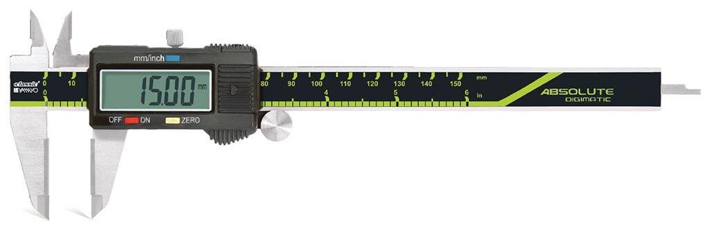
Choose the caliper from the drawing tolerance and feature geometry, not from the label “carbide.” A digimatic carbide jaw caliper combines a digital measurement platform with carbide contact faces; “Digimatic” does not specify accuracy, jaw design, or data compatibility.
| Specification to verify | Why it matters |
|---|---|
| Measuring range | Covers the largest outside, inside, or depth feature without using the jaw tips |
| Resolution and permissible error | Separates display increments from the manufacturer’s actual measurement capability |
| Calibration certificate and traceability | Confirms calibration against stated standards and supports audit records |
| Jaw length, thickness, shape, and carbide-face geometry | Determines access to shoulders, grooves, bores, and narrow features |
| Depth capacity and step-face design | Prevents a range that fits the part but cannot reach its feature |
| Battery type and data output | Confirms operating life and compatibility with a receiver, cable, SPC system, or inspection software |
| Ingress protection and service route | Matches coolant, dust, and washdown exposure and identifies where recalibration will occur |
Do not approve a 0.01 mm display for a 0.01 mm production decision unless accuracy, repeatability, calibration uncertainty, and drawing tolerance support it. Specify inch or millimetre mode and the required reporting unit.
When sourcing digital calipers carbide jaws in Bengaluru, ask Yamayo Instruments for the exact model datasheet, certificate format, traceability details, output standard, and local recalibration route. Reject a carbide contact if it can mark aluminium, plastic, paint, or a sealing face; choose a non-marring method or another gauge instead.
Related product
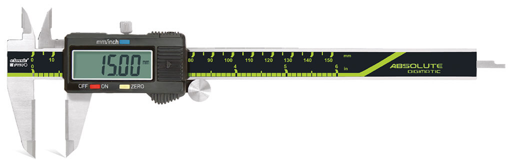 | Calipers Digimatic Calipers with Carbide Jaws Digimatic Calipers with Carbide Jaws The Digimatic Caliper with Carbide Jaws is a precision digital measuring instrument engineered for accurate... View product → |
Frequently asked questions
How do you prepare a part for a carbide-jaw digital caliper reading?
Remove burrs, chips, abrasive particles, and oil from the workpiece and measuring faces. Inspect the carbide inserts for damage before zeroing the caliper.
How do digital calipers with carbide jaws avoid false dimensions?
Keep the jaws square to the feature, use light consistent contact, and avoid forcing the jaws into gaps, chamfers, burrs, or uneven surfaces.
How should you measure depths and steps with a digital caliper?
Place the depth beam or step faces against the actual feature surfaces, keep the caliper aligned, and confirm that burrs or radii are not changing the contact points.
What does carbide improve on a digital caliper?
Carbide improves jaw wear resistance during repeated contact with abrasive or hard production parts. It does not correct contamination, misalignment, excessive force, or damaged inserts.