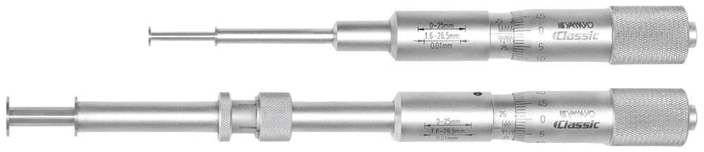
A production buyer must match the measuring face to the feature being controlled: groove width, root diameter, groove depth, flank location, or web thickness. By the end, you will be able to specify the correct geometry and range, reject unsuitable groove micrometer sizes, and define the evidence needed before releasing measurements for production decisions.
Key takeaways
- Match blade and tip geometry to the drawing’s controlled groove dimension.
- Select the measuring range and contact dimensions as one specification.
- Control alignment, pressure, and seating to prevent false groove readings.
- Compare micrometer accuracy with the part tolerance before requesting a quote.
Match the Micrometer Geometry to the Feature on the Drawing
A contact that reaches the groove does not prove that it measures the specified feature. Select the geometry from the drawing’s controlled dimension, then check blade thickness, tip radius, contact width, and clearance from the flanks and root.
| Feature on drawing | Suitable geometry | What to verify |
|---|---|---|
| Groove-root diameter, external | Blade-type or reduced-width groove micrometer | Both contacts seat on the intended root; neither bridges the groove or bears on a flank. |
| Groove-root diameter, internal | Internal groove micrometer with opposed spherical or pointed contacts | The contacts enter the bore groove without touching the bore wall or adjacent shoulder. |
| Groove width | Dedicated groove-width gauge, calibrated form gauge, optical comparator, or vision system | The method locates both flanks; a blade micrometer alone can report a plausible but incorrect width. |
| Flank location or profile | Point, disc, or form-specific contact arrangement | The contact shape matches the datum and flank angle shown on the drawing. |
| Web thickness between grooves | Ball-and-flat, disc, or narrow-anvil micrometer | The faces contact the specified webs rather than dropping into a groove. |
For micrometers for groove measurement, use a narrow blade only when its thickness and tip radius fit the feature without forcing or edge contact. A broad flat-anvil micrometer is better for an exposed shoulder or web, while a comparator or vision system suits groove width at higher volume.
Deburr and clean the part first; a burr can shift the contact, damage a thin blade, and create a repeatable wrong reading. Inspect contact wear before approving production use.
Choose the Range and Contact Dimensions Together
Select groove micrometer sizes by matching two limits: the measured dimension must sit comfortably inside the range, and the contacts must enter without touching unintended surfaces. A 0–25 mm model is not suitable merely because the expected reading is 12 mm; groove width, depth, shoulder clearance, and contact thickness can exclude it.
| Feature or dimension | Range choice | Contact and clearance check |
|---|---|---|
| External groove width or web thickness | 0–25, 25–50, 50–75, or 75–100 mm; choose the band containing the dimension | Use blade, disc, or narrow anvil faces that contact the specified flanks without touching the root |
| Internal groove in a bore | Select the range containing the groove or root diameter | Confirm the point, ball, or blade reaches the groove while clearing the bore and shoulder |
| Deep or recessed groove | Select the next suitable range only after checking reach | Verify spindle reach, throat clearance, minimum groove width, and allowable shoulder distance |
| Inch-dimensioned part | Use the corresponding 0–1 in family, then 1–2 in and successive 1 in bands | Match tip diameter or blade thickness to the drawing’s access space |
Request the manufacturer’s dimensional drawing before ordering. Check minimum groove width, measuring-face thickness or diameter, reach, throat clearance, and shoulder distance against the actual section drawing. Keep the feature away from both range limits when another size fits; this leaves handling margin and avoids forcing the instrument.
A narrow blade reaches tight grooves but suffers more from burrs, edge damage, and angular misalignment. Deburr and clean the part, then inspect the contact for wear; a damaged thin tip changes access and measurement bias. Use a standard outside micrometer only when its anvil geometry contacts the specified surfaces without entering the groove.
Use a Controlled Technique to Avoid False Groove Readings
A reading represents the specified groove location only when the part is clean, the contact geometry is undamaged, and the micrometer is aligned with the drawing’s measurement direction. Use this procedure for micrometers for groove measurement:
1. Deburr and clean the groove, removing chips, oil, and raised metal that could hold a blade or ball away from the true surface. Inspect narrow contacts for bending, edge damage, and wear before use.
2. Set the micrometer to zero, then approach the groove without forcing either contact face. Use the ratchet or friction thimble rather than tightening the thimble by hand.
3. Position the contacts at the specified angular orientation. Keep the spindle and anvil centred on the required root, flank, or diameter location; do not let a blade bear against a flank unless flank contact is part of the specification.
4. Close the instrument with consistent ratchet clicks, then hold it steady. Do not rock the frame, blade, or ball to find a preferred reading: rocking can create a repeatable-looking value from the wrong geometry.
5. Repeat the measurement at the required positions around the part and record the orientation. If readings change with operator pressure or part rotation, use a fixture or guided method instead of accepting the lowest or highest value.
For high-volume production, confirm the technique with a gauge R&R or method study. Operator seating and part-position effects can exceed the tolerance even when the micrometer’s catalogue specifications appear adequate.
Compare Accuracy and Measurement Risk with the Tolerance
A groove micrometer is suitable for production acceptance only when its measurement risk is small relative to the part tolerance. A 0.001 mm display does not prove 0.001 mm accuracy; compare the stated maximum permissible error, repeatability, and calibration uncertainty at the groove dimension being accepted.
Evidence to request:
| Evidence | What it must show | Why it matters |
|---|---|---|
| Accuracy specification | Maximum permissible error across the required range | A reading can be consistently wrong even with fine resolution |
| Repeatability result | Spread from repeated measurements on a representative groove | Reveals variation from contact and operator technique |
| Calibration certificate | Instrument identity, range, measured points, standards, conditions, error, and uncertainty | Links the result to traceable evidence |
| Production check | Results from representative parts, operators, and contact positions | Exposes bias that a bench specification will miss |
Compare the combined error risk with the complete drawing tolerance, not just the nominal size. If the tolerance is ±0.02 mm and the instrument’s documented error plus uncertainty consumes a large part of that 0.04 mm band, a pass/fail decision becomes vulnerable near either limit.
Ask for a guard-band rule before release: define how close to the specification limit a reading requires a second measurement, independent instrument, or quality review. Record the groove location, instrument identification, calibration status, and temperature for traceability. Reject a quotation that offers only “calibrated” or “passed” without measured points and uncertainty.
Write an RFQ That a Local Supplier Can Actually Quote
Give the supplier enough geometry and acceptance data to quote a usable instrument, not merely a nominal range. An RFQ for groove micrometers in Ahmedabad should identify the part, measurement location, and production consequence of a wrong reading.
1. State metric or inch units, the required measuring range, groove type, minimum groove width, groove depth, shaft or bore diameter, and whether the feature is internal or external.
2. Add the feature tolerance and required resolution, accuracy, repeatability, and calibration uncertainty. A 0.001 mm display does not prove that the instrument can accept a 0.010 mm tolerance.
3. Request the manufacturer’s dimensional drawing showing measuring-face thickness or diameter, tip radius, reach, throat clearance, and allowable shoulder distance. Ask the supplier to confirm access at both range limits, not just the nominal range.
4. Describe the expected measurement volume, part material, surface condition, and measurement orientation. State that parts will be deburred and cleaned, and identify any risk from thin blades, burrs, or exposed contacts.
5. Require a calibration certificate with documented traceability, plus delivery inspection details and the stated accuracy specification.
6. Ask about replacement contact geometry, contact availability, repair, recalibration, delivery time, and local technical support. Whether you contact Yamayo Instruments or another industrial groove micrometer supplier in Ahmedabad, these details expose a low quotation that becomes expensive after contact wear.
Attach the drawing or a marked photograph of the groove. That single attachment prevents a supplier from quoting a model that reaches the part but touches the flank or root incorrectly.
Related products
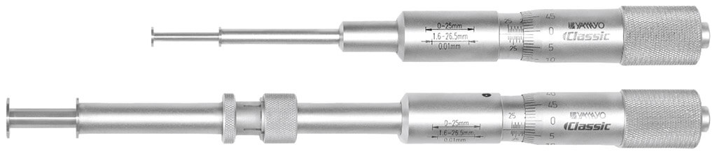 | Micrometers Groove Micrometers The Groove Micrometer is a specialized precision measuring instrument designed for accurate measurement of groove widths, groove... View product → |
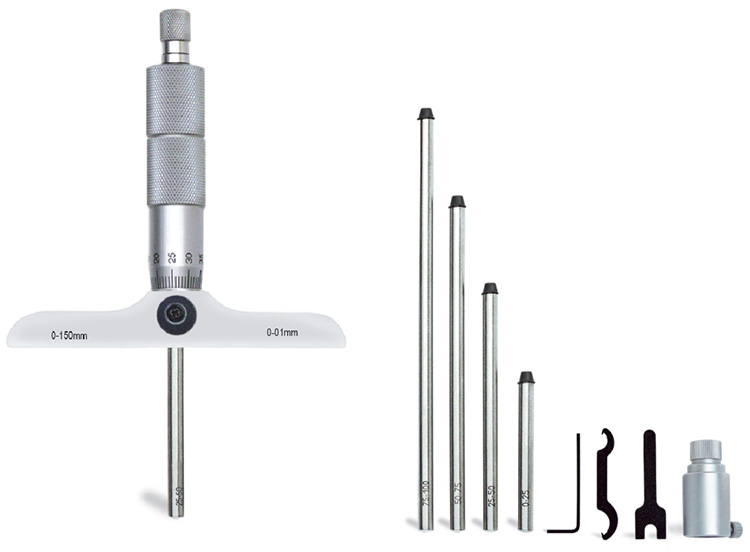 | Depth Measurements Depth Micrometers The Depth Micrometer is a precision mechanical measuring instrument designed for accurate measurement of depths, grooves, slots,... View product → |
Frequently asked questions
How do you match a groove micrometer to a drawing feature?
Identify the controlled dimension, then check blade thickness, tip radius, contact width, and clearance from the groove flanks and root.
How should you choose groove micrometer sizes?
Choose a range that covers the target dimension while confirming that the contact dimensions fit the groove without touching unintended surfaces.
How can you avoid false readings with micrometers for groove measurement?
Clean the feature and contacts, align the micrometer square to the groove, seat it consistently, and use controlled measuring force.
When is a groove micrometer accurate enough for production measurement?
Compare the instrument’s stated accuracy and resolution with the drawing tolerance, then account for alignment, contact, temperature, and operator error.
What should an RFQ for a groove micrometer include?
State the groove dimension, range, contact geometry, required accuracy, resolution, quantity, calibration documentation, delivery location, and inspection conditions.
Related products
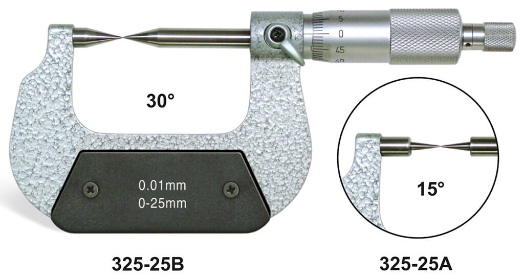 | Micrometers Point Outside Micrometers The Point Outside Micrometer is a specialized precision measuring instrument designed for measuring web thickness of... View product → |
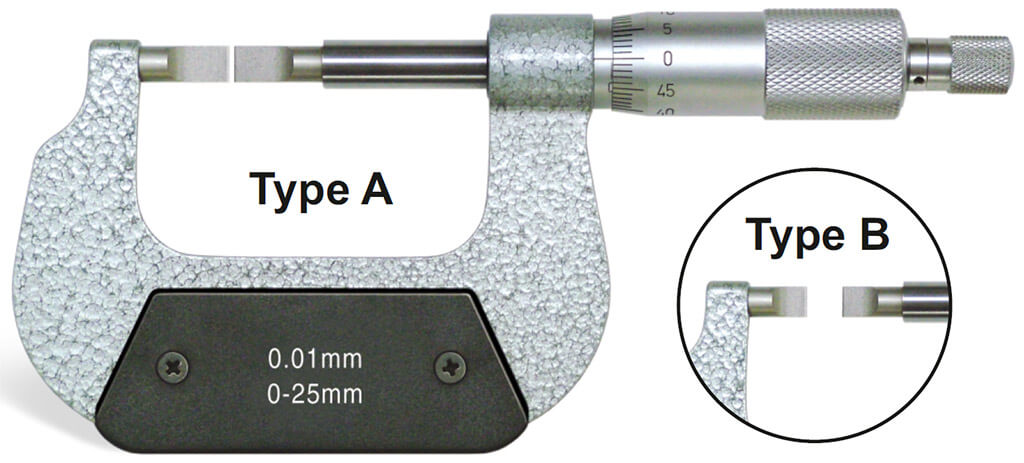 | Micrometers Blade Outside Micrometer The Blade Outside Micrometer is a specialized precision measuring instrument designed for measuring groove diameters, shaft... View product → |
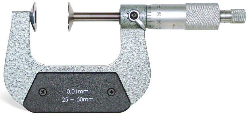 | Micrometers Disc Micrometers The Disc Micrometer is a specialized precision measuring instrument designed for measuring the root tangent length of spur gears,... View product → |
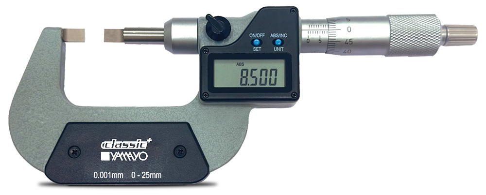 | Micrometers Digimatic Blade Micrometers The Digimatic Blade Micrometer is a precision digital measuring instrument specially designed for measuring groove... View product → |