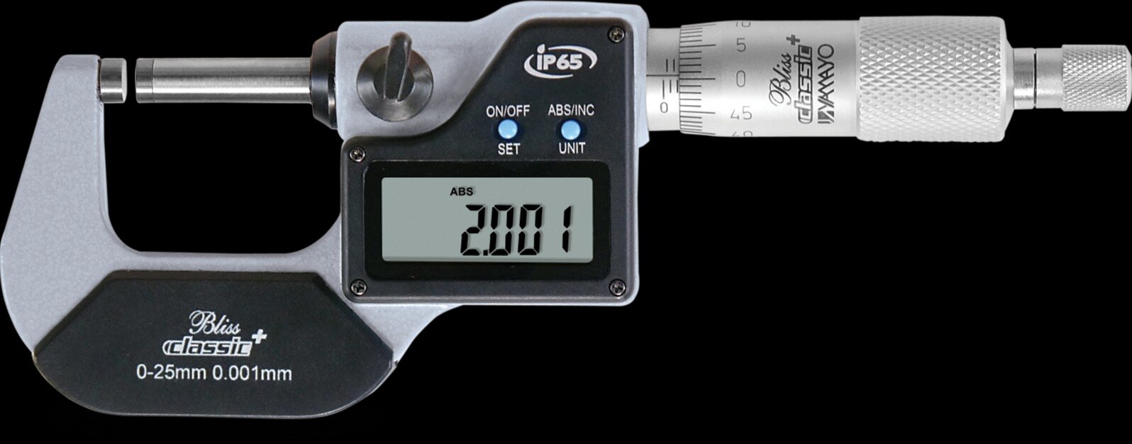
The right micrometer depends first on the feature you must touch, not on the number of digits on the display. By matching contact geometry, measuring range, force control, environmental protection, and production requirements, you can avoid systematic errors that a higher-resolution instrument will not fix.
Key takeaways
- Choose anvil and spindle geometry before display resolution.
- Select a range that keeps the measurement near the micrometer’s middle.
- Use V-anvils, blade anvils, or ball contacts for difficult features.
- Switch tools when access, speed, or operator safety makes micrometer measurement unsuitable.
Start with the feature, access, and contact geometry
A conventional two-flat-anvil outside micrometer fits an accessible shaft, pin, or flat edge with a clean cylindrical or flat contact area. Choose the contact geometry before display resolution: if the anvil or spindle touches a shoulder, radius, thread crest, flute, or burr, finer digits will not correct the error.
| Option | Contact geometry and access | Best fit | Main risk |
|---|---|---|---|
| Conventional outside | Flat anvil and flat spindle; open access | Shafts, pins, plates, and ordinary outside dimensions | A groove, thread, or flute can produce a false large reading |
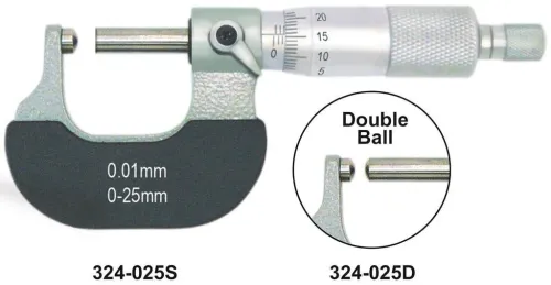
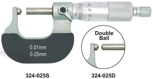
| Point or blade | Narrow pointed contacts or thin blade faces | Grooves, shoulders, slots, and small recesses | The contact can slip off or damage a delicate edge |
| V-anvil | V-shaped anvil with opposing spindle | Round fluted cutters and other multi-flute tools | A standard flat anvil measures different rotational positions differently |
| Tube or disc | Curved, reduced, or disc-shaped contacts | Tube walls, narrow lands, and shoulder locations | The contact may not represent the intended wall or land |
| Thread or spline | Formed contacts matching thread or spline geometry | Thread pitch diameter or spline dimensions | A general-purpose micrometer measures the crest or tooth incorrectly |
For deep features, verify the frame, anvil reach, and spindle clearance as an access envelope. Interchangeable-anvil models help cover varied jobs, but only when the supplied contact set matches the feature; swapping anvils does not make one instrument universal.
Digital micrometers for outside measurement suit contact-based inspection, while rapidly rotating, hot, flexible, or rough parts need a fixture, dedicated gauge, or non-contact method. Choose among outside digital micrometer types by asking where the contacts can sit without interference.
Match the range and specifications to the tolerance
Choose the smallest frame range that fully contains the dimension. A 0–25 mm micrometer does not replace a 25–50 mm model; each has its own frame, spindle, and reference condition. Leave enough travel for the part, but avoid a larger frame that adds weight, cost, and handling error.
| Specification | Choose | Risk if mismatched |
|---|---|---|
| Resolution | 0.001 mm or 0.00005 in only when the stated accuracy supports it | Extra digits can create false confidence |
| Accuracy and repeatability | Compare maximum permissible error and repeatability with the part tolerance | A near-limit result can be falsely accepted or rejected |
| Force control | Ratchet or friction thimble for repeatable contact force | Hand pressure can distort thin, flexible, or soft parts |
| Display | Large, readable digits; inch/mm conversion or data output when required | Poor visibility or transcription creates avoidable errors |
Good digital micrometer selection compares measurement uncertainty and calibration uncertainty with your guard-band policy, not display resolution alone. If uncertainty consumes a substantial fraction of the tolerance, buy a more capable instrument or use a comparator or dedicated gauge; a finer display will not fix the decision risk.
For digital micrometers for manufacturing, stabilise the instrument and part near 20 °C before close-tolerance inspection. A 100 mm steel part 10 °C above that reference can differ by about 11.5 micrometres. Record temperature when it affects acceptance, and do not heat the frame by gripping it for long periods.
Measure shafts, sheets, tubes, and grooves without bias
A micrometer reads high or low when its faces contact the wrong points, sit out of square, or squeeze the workpiece. Digital micrometers for outside measurement need controlled seating more than extra resolution. That is the operating discipline behind how to choose digital micrometers for outside measurements.
- Clean the anvil, spindle, and feature. Remove chips, oil film, burrs, and scale; a burr on a shaft or sheet can create a false oversize reading.
- Place the part squarely between the faces. On a shaft, rock the micrometer lightly through the diameter and record the minimum stable reading. On a sheet, keep both faces parallel and avoid measuring over a dent or edge.
- Keep contact on the intended geometry. For a tube, contact the outside crown rather than a weld bead or damaged section. For a groove, use the correct narrow or pointed contact; a flat face touching a shoulder or radius gives a position-dependent result.
- Close the spindle with the ratchet or friction thimble until it slips consistently. Do not tighten the frame by hand, because force can flatten thin tubing, flex a sheet, or distort a soft surface.
- Let the part and instrument reach the 20 °C reference temperature. A 100 mm steel part 10 °C warmer can differ by about 11.5 micrometres; hold the frame by its insulated grip, not around the frame.
- Take repeated readings at marked positions and record the location. A changing result points to runout, taper, misalignment, or inconsistent contact—not a display problem.
Know when a digital micrometer is not the fastest or safest tool
Choose a digital micrometer over a vernier or mechanical micrometer when fast, unambiguous readings, inch–millimetre conversion, or data output matters in repeated inspection. Digital micrometer selection still depends on the feature: a finer display does not correct poor contact or misalignment.
| Option | Choose it when | Do not choose it when |
|---|---|---|
| Digital micrometer | You need contact measurement with quick readings and repeatable operator handling | The part is hot, rotating, flexible, rough, or changing rapidly |
| Vernier or mechanical micrometer | Battery-free operation, ruggedness, and direct mechanical feedback matter more than speed | Operators must record many readings or switch units frequently |
| Digital caliper | You need fast checks across outside, inside, depth, and step features | The tolerance demands micrometer-level contact control |
| Comparator | You are comparing many similar parts against a master or setting | You need the actual dimension without a reference standard |
| Height gauge | The feature must be located from a surface plate or datum | Handheld access and rapid part-to-part checks are the priority |
| Dedicated snap gauge | Production volume demands fast, repeatable go/no-go decisions with low operator judgement | You need several dimensions or occasional, flexible inspection |
Use a dedicated gauge for the safest high-volume check when its fixed contacts match the feature. Choose a comparator for speed, or a height gauge for positional work; choose the digital micrometer for versatile, traceable contact measurements.
For digital micrometers for manufacturing, confirm the tool cannot touch a shoulder, burr, or rotating surface before selecting it.
Turn the choice into a purchasing and inspection checklist
Before ordering, make the acceptance decision explicit: define the feature, tolerance, production rate, environment, and required measurement uncertainty. Your purchasing record should explain how to choose digital micrometers for outside measurements, not simply request the highest displayed resolution.
1. Confirm the contact geometry and access envelope. Reject any model whose anvil and spindle touch a shoulder, radius, thread crest, flute, or burr.
Compare outside digital micrometer types for the job: standard faces for broad surfaces, point faces for narrow grooves, tube faces for curved walls, and interchangeable designs only when the anvil set reaches every required feature.
2. Select the smallest frame range that fully contains the dimension. A 0–25 mm micrometer does not replace a 25–50 mm model; leave enough travel to seat the workpiece without forcing it.
3. Compare maximum permissible error, repeatability, calibration uncertainty, and resolution against the tolerance and your guard-band policy. A 0.001 mm display does not make a several-micrometre error acceptable.
4. Specify ratchet or friction-thimble force control, a readable display, unit conversion, data output, and an IP rating when coolant or washdown is present.
5. Require calibration records, traceability, operating temperature, battery details, and replacement contact specifications.
6. Record a method: stabilize part and instrument at 20 °C, avoid heating the frame, and document temperature when it affects the decision.
Digital micrometer selection should also test production speed. Ask Yamayo Instruments to confirm whether the proposed model, fixture, or dedicated gauge gives repeatable operator-independent results for your actual cycle.
Related products
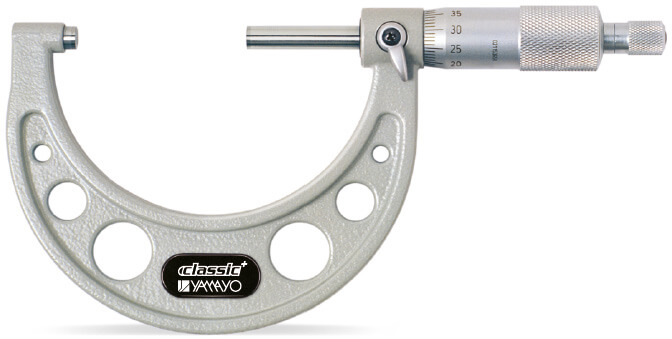 | Micrometers Outside Micrometers The Outside Micrometer is a precision measuring instrument designed for accurate external dimension measurement of components,... View product → |
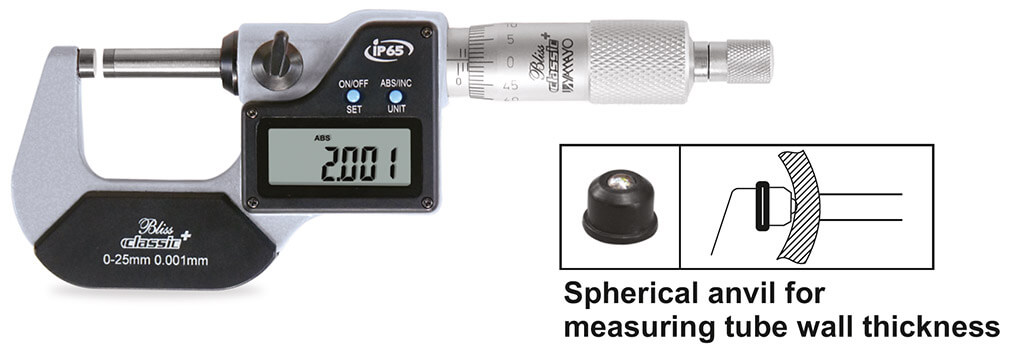 | Micrometers Digimatic Outside Micrometers The Digimatic Outside Micrometer is a high-precision digital measuring instrument designed for accurate external... View product → |
Frequently asked questions
How do you choose a digital micrometer for outside measurements?
Start with the contact geometry and access, then match range, resolution, accuracy, and measurement force to the feature and tolerance.
Which outside digital micrometer type suits shafts, sheets, tubes, and grooves?
Use a standard flat-anvil micrometer for accessible shafts and flat edges; choose blade, ball, V-anvil, or tube micrometers when feature shape demands it.
When is a digital micrometer the wrong tool for outside measurement?
Choose calipers, an outside diameter gauge, a bore gauge, a comparator, or a coordinate measuring machine when access, speed, feature shape, or inspection volume exceeds micrometer capability.
What should you check before purchasing digital micrometers for manufacturing?
Confirm range, resolution, accuracy, repeatability, ratchet or friction thimble, data output, protection rating, calibration documentation, and compatibility with your inspection process.
Related products
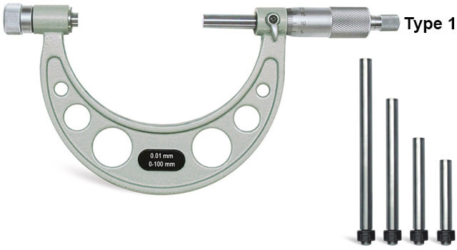 | Micrometers Interchangeable Outside MicrometersMicrometers Interchangeable Outside Micrometers The Interchangeable Outside Micrometer is a versatile precision measuring instrument designed for accurate... View product → |
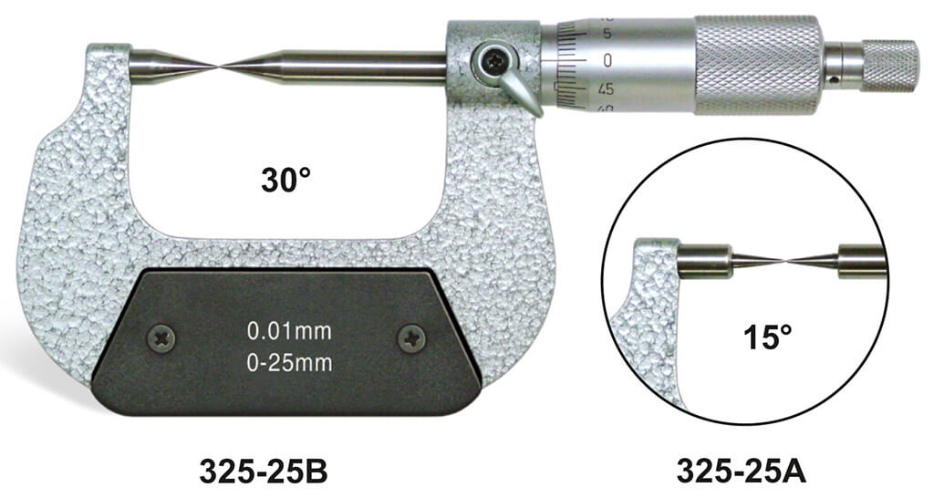 | Micrometers Point Outside Micrometers The Point Outside Micrometer is a specialized precision measuring instrument designed for measuring web thickness of... View product → |
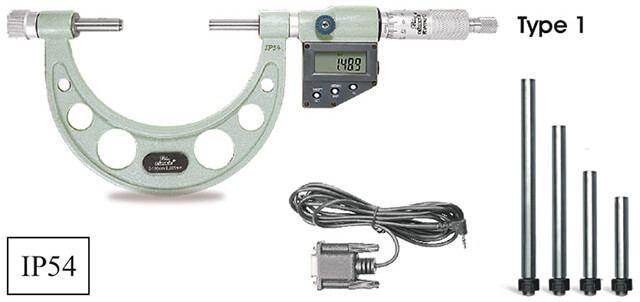 | Micrometers Digimatic Interchangeable Outside Micrometers Digimatic Interchangeable Outside Micrometers The Digimatic Interchangeable Outside Micrometer is a high-precision digital measuring instrument... View product → |
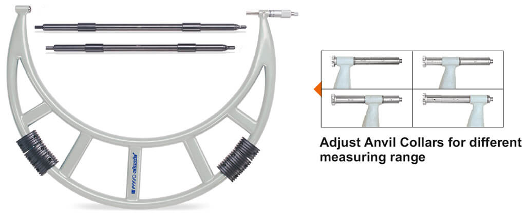 | Micrometers Adjustable Outside Micrometers Adjustable Outside Micrometers The Adjustable Outside Micrometer is a precision measuring instrument designed for accurate measurement of large... View product → |